Continue to Site

Welcome to our site!

Electro Tech is an online community (with over 170,000 members) who enjoy talking about and building electronic circuits, projects and gadgets. To participate you need to register. Registration is free. Click here to register now.

  • Welcome to our site! Electro Tech is an online community (with over 170,000 members) who enjoy talking about and building electronic circuits, projects and gadgets. To participate you need to register. Registration is free. Click here to register now.

Dark detector

Status
Not open for further replies.
Mike just before I leave this ,for another application I have in mind , what would be involved in making one that turned on with the light and off with the dark?.
The opposite of this?

I was stewing over something that draws power only during the daylight hours as a solar installation would be suited to putting power to use as made rather than storing it in the battery and losing some before it gets used at night.
 
It dawned on me a litle later that if I switch the positions of the trimpot and LDR it might work the opposite way so I made a sim to reflect that and indeed with the value of the new LDR's I have ordered it does seem to give a result
 

Attachments

  • LightSensor.asc
    3.1 KB · Views: 308
Turns out there is little need for all the complexity and components ! This given in Transistor amplifiers on Talking Electronics site is quite adequate-Don't understand why they want too show off their knowledge and waste your time making a simple thing complex .

Clearly you pose the question to get an answer but its not coming on this forum. Its gone haywire

http://www.talkingelectronics.com/p...mplifier/TheTransistorAmplifier-P2.html#Relay
The following circuits are NOT high-speed, but will activate a relay successfully.
Fig74a.gif
Fig 74a.

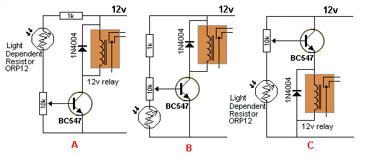
..............Turns ON with light ....... Turns ON with dark

Circuit A activates the relay when light falls on the LDR. The level of illumination can be adjusted by the 10k pot.
Circuit B activates the relay when the illumination reduces. The level can be adjusted by the 10k pot. Circuit C is an emitter follower and although it works in a similar way to circuit B, the voltage on the collector is less than 12v by about 1v and this creates extra loss and added temperature-rise in the transistor.
 
Last edited:
That is great, I am glad that you have found a simple solution.
Have you actually built and tested it yet?

JimB
 
Yes thanks Jim I have built and tested about 6 different circuits with variable complexities but the A circuit here with a BC 550 transistor of 50 volts seems to be going well at 24Volts. I have two of the Dark Detectors installed and working fine too . I needed the light detector circuit because one installation has a very dark interior and I didn't want the circuit out in the weather.
 
That is interesting because the circuit which you are using now is similar if not identical to the one which you started with and runs the risk of sitting in a half on - half off state with the transistor getting hot, as happened with your original build.

JimB
 
Just had a quick look at the BC550 datasheet, it has a much higher current gain that the 2N2222, which means that it is likely to go into saturation much quicker that the 2N2222 used in the original circuit.

JimB
 
Turns out there is little need for all the complexity and components ! This given in Transistor amplifiers on Talking Electronics site is quite adequate-Don't understand why they want too show off their knowledge and waste your time making a simple thing complex .

Clearly you pose the question to get an answer but its not coming on this forum. Its gone haywire

http://www.talkingelectronics.com/p...mplifier/TheTransistorAmplifier-P2.html#Relay

...

Sorry that we are complicating your life. However, as with most advice and circuits you download off the internet, you get what you pay for...
IMHO, the talkingelectronics circuits are typical of the crap that is posted on the Internet!

As pointed out by Jim, the talkingelectronics circuits you posted have exactly the problem that brought you to this forum in the first place. Namely, as the sun goes up or down, the LDR resistance changes slowly, so the transistor turns on and off very slowly, and in the process, it goes through a region where it is dissipating a substantial amount of power, and is getting quite hot. That is exactly the problem that the (too complicated) Schmitt trigger circuits solve.

The only thing that keeps the transistor from burning itself up and self-destruction is that you happen to be using a fairly sensitive relay (if it is still the 12Vdc one with the 320Ω coil that you posted earlier). If you used a less sensitive relay, like the typical "automotive" 12V relay with the 85Ω coil, you would be replacing the transistor every day....

Let me use your nemesis, LTSpice, to show you the problem with the talkingelectronics circuits:

Light.gif


Here, I simulate the changing LDR resistance vs time. It is dark (200KΩ)at 0s and 200s. It is light (2K) at 100s. See the Green trace. I plot the actual LDR resistance divided by 10,000 to get it to scale onto the plot axis. I just picked a pot position (50%) that causes the transistor to go from fully-off to fully-on as the LDR goes from 200KΩ (20V on the plot) to 2KΩ (0.2V on the plot) and back again.

The red trace shows the voltage across the relay, which I guess is one similar to this one at DigiKey. Note if you download the data sheet, the relay coil properties are as shown on the schematic. Again, I assume that you want to run the circuit on 24V, but the relay is actually a 12V one, so I put the 330Ω resistor R2 in series with it.

The published pull-in voltage of said relay is 8.4V, so I use cursor1 on the plot to mark that voltage. Note that happens at 44s when the LDR resistance is about 110KΩ. This relay drops-out at 1.2V, so cursor2 marks that at 180s, where the LDR resistance is 160K.

The problem with this simplistic circuit is shown in the lower plot pane where I plot the power dissipation in Q1 (the light blue trace), where as the LDR resistance decreases from 200KΩ toward the relay pull-in value of 110KΩ, the transistor begins turning on and self-heats due to the power being dissipated in it long before the relay pulls-in. Note that the peak dissipation is ~0.24W, which is within the maximum rating of a TO92 plastic package, but will get hot enough to burn your fingers if you were to touch it. Note that the transistor gets hot again just before the relay drops out. Again, this is exactly the issue that the Schmitt Trigger version of the circuit solves... Note that if you used a relay with a lower coil resistance, like the typical Automotive relays, you would get the transistor so hot that it would self destruct.

I also plot the power in the relay (dark blue) and power in R2 (violet). Note that R2 should be a 1W power resistor.
 
Last edited:
I thought when I posted above that you might be offended . I can be a bit abrupt and direct at times I suppose and I didn't mean the post as an affront .
I came here for an answer . Eric hinted , alec suggested and you provided another circuit . I appreciate the help in all of that as I do appreciate your efforts above .

However I came here for an answer to apply to a problem .I am engaged in installing LED spotlights , movement and daylight sensitive in 24V only and want to get it done . I did not want to have to learn LTSpice programming and operate the program to be able to fix my problem . Generally I don't have a windows machine to run anyway but in this case I did and LTSpice diagrams were all that was available . No doubt they explain and work well in your situation . They are not so good in mine.

Ill have a look at the above and see if I can understand your points . I still need a light sensor in one situation because it is so dark in there during the day that the relay is on almost 24 hours so the lights drain the batteries.

Would you consider altering your schmidt trigger circuit for me to make it a light sensor please Mike ? Your circuit is very useful as is and you will notice that I have posted a reference to it in the alternative energy thread where I know it is needed in the field . A lot of these 24 V spotlights have been sold here and the PIR's sold with them were rubbish meant for 12 Volt and blew up .They had a 12 V zenner which was sometimes good enough but 9 out of 10 not good enough and blew other components . Who has time to fix them? Thats where the relays came from. I have about 12 of them all from dead boards

I fiddled with trying to make the circuit into a light sensor but my knowledge is just not good enough hence I am here with hat in hand..

I have had a good shot at trying to master LTSpice in front of the computer, time that I don't have to waste made by depriving myself of sleep. I attach a spice file that I was throwing various values into but I don't understand what it is telling me .

Your file was not attached so I could not pull it down . My eyes are shot and I cant see the traces on the screen grab so well but I understand your points now . Isn't the 1K to avoid idiots like me that pull the pot down to zero? I guess you are working on the assumption that the LDR never gets to zero.
 

Attachments

  • relaytrannyldr.asc
    1.3 KB · Views: 296
Last edited:
...
However I came here for an answer to apply to a problem .I am engaged in installing LED spotlights , movement and daylight sensitive in 24V only and want to get it done .... I still need a light sensor in one situation because it is so dark in there during the day that the relay is on almost 24 hours so the lights drain the batteries.
... A lot of these 24 V spotlights have been sold here and the PIR's sold with them were rubbish meant for 12 Volt and blew up .They had a 12 V zenner which was sometimes good enough but 9 out of 10 not good enough and blew other components . Who has time to fix them? Thats where the relays came from. I have about 12 of them all from dead boards

Just so I understand. Keep your answers simple...

1. You have some sensitive 12V relays (400 Ohm coils)?

2. You have some LDRs that are ~200KΩ dark, about 2KΩ in direct sun, about 10K at the light level where you want to switch?

3. You need to switch on a load when it is daylight?

4. The circuit needs to operate from 24Vdc?

5. The circuit should be low power at night? (You accept that the relay sucks power when the relay is on)?

6. Finally, if battery operation is required, do you even need to use a relay? Can it be eliminated by having the light sensor switch the PIR/LED spotlight directly? If so, how much current does the 24V spotlight require?
 
Last edited:
1/ Yes
2/ Yes-Got new LDR's 250K dark about 1 K full light Need to switch at as dark as possible
3/ No the load must be switched on when it is dark and off whenever lights are not needed ie Dark
However something that consumes power during day might be better ie NC contact held open during day lets go at night Lights on NC terminal might work well
4/ Yes
5/ No No/Low power in the day whenever light is sensed.
6/ The LED spotlights and PIR sensors pull about 120 mA when settled . Some have two sets of load on them so double that.
I am not sure what the instantaneous load draw is to start them up but the PIR's switch on for 2 minutes (so does the Spotlight) when first switched on.
I can run the LDR separately to the outside but it just means more wiring . I'm doing doing that at present.

These are all battery operated at 24Volts and recharged by solar panels putting out 36 Volts peak. So it would be possible to build something that senses the incoming voltage from the panels . I'm trying to keep it all on one panel next to the batteries thats why its sometimes dark in there. They are in sheds and boats
 
Last edited:
Working on it....
 
Hope I got it this time. Refer to the schematic: Note that this version turns the previous circuit upside down, using a PNP first and an NPN second. The forward Voltage drop of the LED is used as a voltage reference.

MyNite.gif

As before, the relay is pulled-in during the day when there is plenty of sunlight to charge the batteries and you can waste a little power for the relay. You will have to use the NC contact on the relay to power lights at night.

Using your specified 12V relays, I came up with a way of reducing the operating power to only 16mA during the day, and 250uA at night when the relay is not energized.

See C1 and R5. The relay is energized as the SchmittTrigger switches, 24V momentarily appears across the 12V relay coil, pulling it in with a snap. As C1 charges, the voltage across the relay drops to ~6V in about 70ms. 6V is more than enough to hold the relay closed for the rest of the day. R5 wastes much less power than before. I tried this on the workbench with a similar relay I have here.

I worked on making the circuit adjustable over a wider range of LDR resistances. With the 10KΩ TrimPot (Rt/Rb) as shown, as the pot is adjusted from end to end, the trip points move from LDR resistance =~10KΩ to 120KΩ. The simulation shows X=0.5, pot centered.

The upper plot shows LDR resistance vs time, going from night to day to night to day. The lower plot shows the current that the circuit draws, 15mA of which goes through the relay. Note that with the pot centered, the LDR resistance trip points are 68KΩ pull-in and 81KΩ release.
 

Attachments

  • MyNite.asc
    3.5 KB · Views: 253
Thanks very much Mike . I'll study it and make it a few times like the first . I have 5 of the first on vero board and a DIYLayoutCreator file made up of the first which I will put on the RE thread when I am happy with it . I'll do the same with this when I get it working . Appreciate the time taken Mike!
 
So Mike I have built two variations of this new circuit now with the components I can lay hands on. Both no go as yet so I thought to ask what I should see .

relay stays on all the time . Getting the LDR really dark the led goes out but not the relay. Held it dark for about 10 seconds each time . All the voltages I can test look right and plugging my values in doesn't seem to change anything in the sim.

My Q1 is a BC548 , R2 and R3 are 12K .R5 is 1K Otherwise identical. I'll keep going over the layout but I think I have it right .Its like in the pic below I hope..
MyLite.png
 
Last edited:
Looks like D1 is backwards.

Q1 is the NPN that drives the relay on my schematic, you have it labeled Q2? Is it really a NPN?

Q2 is PNP that is nearest the trimpot on my schematic, you have it labeled Q1? Is it really a PNP?

The copper trace under R4 is cut?

Top trace is +24V? Bot trace is 0V?

VR1 is 10K?
 
Looks like D1 is backwards. My eyes are not able to see the flat at times .Merely a rotate Ill fix it

Q1 is the NPN that drives the relay on my schematic, you have it labeled Q2? Is it really a NPN?
You must have got to it while I was editing it Q1 is the relay driver and it is NPN.Perhaps you get an email or something. I edit posts all the time .Hate to have the content sloppy or wrong

Q2 is PNP that is nearest the trimpot on my schematic, you have it labeled Q1? Is it really a PNP?
As above Q2 is the LED driver and is PNP
The copper trace under R4 is cut? Yes

Top trace is +24V? Bot trace is 0V? Yes

VR1 is 10K? Yes marked 103
My choice of coils is going down now .I used one in another circuit which measured 1640 Ohms and tried another at 178 Ohms with the same results . The same values tried in the sim still switch the sim. I have yet to investigate why such a high reading on the coil in circuit.
I have tried the circuit with both relays-both stay ON.
I have checked both transistors with a multimeter
My working notes are below

ScanofMyLitePlay.png
 
Last edited:
Status
Not open for further replies.

Latest threads

Back
Top