Continue to Site

Welcome to our site!

Electro Tech is an online community (with over 170,000 members) who enjoy talking about and building electronic circuits, projects and gadgets. To participate you need to register. Registration is free. Click here to register now.

  • Welcome to our site! Electro Tech is an online community (with over 170,000 members) who enjoy talking about and building electronic circuits, projects and gadgets. To participate you need to register. Registration is free. Click here to register now.

Custom generator magnet size

Status
Not open for further replies.

Njguy

Member
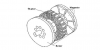
I am making a little dc generator. The generator is arranged in an axial flux configuration, similar to the ones you find in homemade windmills. Similar to this photo, **broken link removed**. I am going to have the coils wrap around iron cores. I was wondering, for the permanent magnets on the rotor, should they only be as large as the iron cores? I am assuming that the coils will only produce voltage from flux traveling through the center of the coils (the core). If the magnet was larger than just the core some of that flux would be traveling through the copper instead of through the center. Would this just be an inefficiency?
 
In terms of making best use of the magnet's field I would assume matching the size of the magnet to that of the core face which the magnet passes would be most efficient.
 
I suspect the optimal design is complex. At least, there are lots of papers on the subject. However, to the point of whether the magnets should be the same size as the core projections, I don't see the advantage. The coils will still be passing through the field. Here is an example (source: **broken link removed** ).
upload_2013-10-29_7-57-45.png


John
 

Attachments

  • upload_2013-10-29_7-54-39.png
    upload_2013-10-29_7-54-39.png
    66.1 KB · Views: 229
I suspect the optimal design is complex. At least, there are lots of papers on the subject. However, to the point of whether the magnets should be the same size as the core projections, I don't see the advantage. The coils will still be passing through the field. Here is an example (source: **broken link removed** ).
View attachment 81690

John

I found this company (yasa motors), and they have three different designs as you can see from the pictures, I am can't figure out which is the most efficient.

https://www.treehugger.com/cars/new-electric-motor-is-50-smaller-but-has-2x-more-torque.html
 
I only see two designs. In this axial design, which seems to be what you are trying to make, the magnet faces are larger than the core faces around which the coils are wound. I thought that answered your question.

upload_2013-10-29_11-33-26.png


That link didn't provide much solid information. I did go to the Oxford site linked therein and searched on Woolmer (**broken link removed** ), but all that came up was a similar press release with even less information.

John
 
The design involves many parameters as you know, however I suspect that what you say may cause inefficiencies as the flux from the magnets through the copper may cause a shading effect reducing the o/p and possibly braking the rotor for no extra o/p.
 
Status
Not open for further replies.

Latest threads

New Articles From Microcontroller Tips

Back
Top