Continue to Site

Welcome to our site!

Electro Tech is an online community (with over 170,000 members) who enjoy talking about and building electronic circuits, projects and gadgets. To participate you need to register. Registration is free. Click here to register now.

  • Welcome to our site! Electro Tech is an online community (with over 170,000 members) who enjoy talking about and building electronic circuits, projects and gadgets. To participate you need to register. Registration is free. Click here to register now.

Counter circuit used to switch an encoder chip

Status
Not open for further replies.
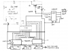
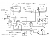
OK, The receiver has the same data and encoding options as the transmitter. So, This makes things a little simpler. Here is a link to the receiver IC datasheet.

I will take a look at the attachment above and reply on it later.

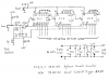
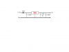
Here are a couple pics of the receiver board.
**broken link removed**

Sean
 
Back to square one

Due to some enlightening PM from Len, I am back to where we started.

The plan now is to get the counter put back together on the proto board, I took it apart when I thought I could use the counter kit I found at Circuithut.com

When I get the counter put back together I will be trying to integrate it with the Tx. Len, One of your PMs said I would have to unsolder some stuff on the Tx board. Does this still apply?

Sean
 
0RESET0 said:
Due to some enlightening PM from Len, I am back to where we started.

The plan now is to get the counter put back together on the proto board, I took it apart when I thought I could use the counter kit I found at Circuithut.com

When I get the counter put back together I will be trying to integrate it with the Tx. Len, One of your PMs said I would have to unsolder some stuff on the Tx board. Does this still apply? I don't recall this comment, can you please find it and quote which page it is on in your next post? I don't want to have to search the whole thread to find it.

Sean
Sean,
Do you have a circuit of the counter kit?

It may be possible to convert it to count in BCD. What counter ICs are on it?
 
Len, you made the comment in the first "another suggestion" PM that you sent me. Here is a copy of the line that I am talking about.

Is your circuit similar to that shown in the "UHF band 4 data transmitter circuit is recommended" (strange English) diagram?

ie. with the diodes going to pin 18 and the 2.7k & 10k resistors on the IC inputs (as shown in this diagram).

If so, then it will be safer (when you measure the high level current) if you disconnect the mid point of these resistors from the inputs (which you would have to do anyway) and connect the + probe of your MM Set for current) to the mid point of one of these resistor pairs. This will reduce the voltage applied to the inputs (via the MM) to a safe level.

My Tx actually has a variation on this diagram. It has jumper pins instead of switches shown and there is only one resistor in that section.

Sean
 
I am putting this in a separate post because the last one was getting big.

So, I do not think we can use the CircuitHut.com counter kit because it only has one IC on it. It is probably doing some kind of MUX. Besides, I only need the three digits that we already have.

I have my counter circuit put back together and it is working again.

I have noticed something lately, both before I took the counter apart and now that I have put it back together. When I first turn the circuit on, the up and down buttons will act funny. If I hit the up button it will either jump to 2 from zero or it will show 1 and then go back to 0 when I let go of the button. the weird part is that if I leave it alone for about a minute then the counter works properly with no errors. :confused: Any Ideas what could be causing this? I may have found something on this. At the same time the problems started, I put the receiver on the board so that I could borrow the power supply. I have only tried this once but when I took the receiver off of the board before putting turning the counter on, I did not have the problems I mentioned. However, when I put the Rx back on the board, it did not cause the problems.

I am now back to waiting for the funds to put in another order to the parts store. I still need to get the three buffers. I am going to get everything else I need at the same time to save on shipping . So, It will be a couple weeks before I can place the order. Even 0.83 cent items get expensive when you have to get 100 of them. :eek:


Sean
 
0RESET0 said:
My Tx actually has a variation on this diagram. It has jumper pins instead of switches shown and there is only one resistor in that section.

Sean
The PM was about measuring currents and voltages. This is not necessary now.

So you won't have to unsolder anything.

You can make a plug by cutting an IC socket in half and then plug it into the C pins. This will be much easier than trying to solder wires to the pins.
 
0RESET0 said:
I have my counter circuit put back together and it is working again.

I have noticed something lately, both before I took the counter apart and now that I have put it back together. When I first turn the circuit on, the up and down buttons will act funny. If I hit the up button it will either jump to 2 from zero or it will show 1 and then go back to 0 when I let go of the button. the weird part is that if I leave it alone for about a minute then the counter works properly with no errors. :confused: Any Ideas what could be causing this? You said you're using 74F counters. As I told you, these are very fast and also most sensitive to noise than the CMOS counters. So it could be a noise issue - from what you say below, it sounds like the noise was coming from the Rx.
I may have found something on this. At the same time the problems started, I put the receiver on the board so that I could borrow the power supply. I have only tried this once but when I took the receiver off of the board before putting turning the counter on, I did not have the problems I mentioned. However, when I put the Rx back on the board, it did not cause the problems.

I am now back to waiting for the funds to put in another order to the parts store. I still need to get the three buffers. I am going to get everything else I need at the same time to save on shipping . So, It will be a couple weeks before I can place the order. Good as I am still thinking about the design. See below. Even 0.83 cent items get expensive when you have to get 100 of them. :eek: Some suppliers offer a discount for larger quantities.

Sean
There may be some variations from what I posted before. I thought I made that point in an earlier post or PM. So give me a day or 2 to finalise. (I'm busy with other work)
 
OK, Len, we have gone thru so many possibilities in the last few posts that I think it is necessary to restate what we are working with. I currently have a circuit built exactly to the specs stated in the attachment from your post on 20th September 2007, 10:58 PM.

IC Components are:
74HC132 Quad Schmidt Trigger NAND (1) (For the debounce)
74HC190 up/down decade counter (3)
SN7447AN Display Driver (3)

If I could draw a schematic to save my life, I would attach a new one.

Len, take your time, I am going no where until I can put in another order. I will spend the time trying to figure out a PCB for this thing.

Sean
 
Sean,
I have made some small changes & improvements to the circuits and added a power supply. See attachments.

I have left Eric's computer interface. You can delete it if you wish.

You'll also need

2 x 74HC05 Hex o/c inverting buffers

1 x 74HC73 Dual JK Flip Flop

Let me know if you can't obtain either of these and I suggest an alternative.

I'll calculate the component (eg. resistor) values tomorrow.
 

Attachments

  • TX driver.PNG
    TX driver.PNG
    86.4 KB · Views: 531
  • Display driver.PNG
    Display driver.PNG
    106.2 KB · Views: 808
  • Decade Counter.png
    Decade Counter.png
    106 KB · Views: 653
  • 5V power supply.png
    5V power supply.png
    2.4 KB · Views: 237
Len,
I wasn't expecting you to reply for a couple days. It looks like you put a lot of thought into this.

I see that you updated the counter schematic to feed into a circuit that is intended for the original display that I had. I am no longer using this display because having the 21 resistors seemed simpler than the modulo thing. We covered this once a while ago.

Is the power supply you drew up more efficient than the power regulator that I am using now, just the TA7805S? I assume the caps are to clean it up.

I figured I would use a 9v battery to power the counter, I might even think of using a small 6v cell like the 12v cell that is in the Tx now. This would be separate from the 12v running the Tx. Will this still work with your PS design?

Thanks for all of your hard work on this project, I am going to stencil the back of the receiver so that you get credit.

Sean
 
0RESET0 said:
Len,
I wasn't expecting you to reply for a couple days. It looks like you put a lot of thought into this.

I needed some breaks from the work I've been doing. Besides most of the design was finished, just needed a spruce up.

I see that you updated the counter schematic to feed into a circuit that is intended for the original display that I had. I am no longer using this display because having the 21 resistors seemed simpler than the modulo thing. We covered this once a while ago. I had forgotten that. Now I understand your PMs.

Is the power supply you drew up more efficient than the power regulator that I am using now, just the TA7805S? I assume the caps are to clean it up.
I don't know what the TA78055 is. if it is working, then leave it alone.

I figured I would use a 9v battery to power the counter, I might even think of using a small 6v cell like the 12v cell that is in the Tx now. This would be separate from the 12v running the Tx. See below Will this still work with your PS design? I don't know what PS means.

Thanks for all of your hard work on this project, I am going to stencil the back of the receiver so that you get credit. You're welcome, it has been an interesting project.

Sean
Sean,
You could simply use a 6 Volt battery with 2 diodes (1N4004 or similar) in series to reduce the voltage to about 5 Volt.

The Tx can operate with a 12 Volt supply while the rest operates from 5V. I think this may what you are asking about re the "PS".

BUT, be sure to connect the ground lines together.
 
Last edited:
Sorry, PS= Power Supply.

So I can have two batteries but I need to make sure that the grounds are tied together. I think I can handle that.

I am not set on the 6v cell, I would have to figure out how long the circuit would run on the meager Ah those things have. I like the idea of not needing to include the voltage regulator that I am currently using, that is what the TA7805S is. Your circuit for a power supply included a 7805, I assumed they were the same thing. Was I right about the capacitors? Are they there as stiffening caps like in the counter circuit?

Sean
 
0RESET0 said:
Sorry, PS= Power Supply.

So I can have two batteries but I need to make sure that the grounds are tied together. I think I can handle that.

I am not set on the 6v cell, I would have to figure out how long the circuit would run on the meager Ah those things have. I like the idea of not needing to include the voltage regulator that I am currently using, that is what the TA7805S is. Your circuit for a power supply included a 7805, I assumed they were the same thing. Yes Was I right about the capacitors? Are they there as stiffening caps like in the counter circuit?
The 220 nF is required for stabilty of the 7805. The 100 uF in parallel with it is to store charge for current peaks. You don't need the 100 uF on the left for a battery powered unit. I posted a copy of a PS I designed for a mains supplied PIC programmer.

Sean
If you want to minimise the battery consumption, you should use an LCD display.

For example, see the www.jaycar.com site and search for Cat. ZD-1886.

This operates from 3 Volt, so you could run the counters etc. from 3 V also.

However, it will need a back light as I assume you'll be doing it in the dark.
The JayCar catalogue that I have does not indicate whether this one has a back light. I expect that Mouser will have something similar.
 
ljcox said:
If you want to minimise the battery consumption, you should use an LCD display.

For example, see the www.jaycar.com site and search for Cat. ZD-1886.

This operates from 3 Volt, so you could run the counters etc. from 3 V also.

However, it will need a back light as I assume you'll be doing it in the dark.
The JayCar catalogue that I have does not indicate whether this one has a back light. I expect that Mouser will have something similar.

I think I will save the back lit LCD for Version 2. After I use this Tx for a couple years, I will scavenge it for parts and go all out. PIC, IndiGlo, and memory so that I can leave the computer at home and still have computer controlled timing.

OH and two way communication so I know if I have continuity at the receiver.

Sean
 
Last edited:
0RESET0 said:
I think I will save the back lit LCD for Version 2. After I use this Tx for a couple years, I will scavenge it for parts and go all out. PIC, IndiGlo, and memory so that I can leave the computer at home and still have computer controlled timing.

OH and two way communication so I know if I have continuity at the receiver.

Sean
Understood.

What display driver are you using? I assume it is the 7447 which is power hungry. A CMOS driver would be better.

Are your displays common anode or common cathode? I assume the former as these match the 7447, but want to check.

You'll need to learn about PICs and buy (or build) a programmer/tester
 
Yes, I am using a 7447 display driver and common anode displays.

I placed an order yesterday that includes the 74LS07 interface buffers. These and a few other parts should be here on Wednesday.

I have been trying a few different PCB design programs and I am not having much luck. Since I will only be needing one PCB, is there a place that I can send a schematic and size restrictions to and have a PCB designed and made? In my past systems, I have had a clear panel so that you can see the internals. It is kind of a signature. So, a company that can make a unique looking PCB and still be functional would be a plus.

Sean
 
0RESET0 said:
Yes, I am using a 7447 display driver and common anode displays.

I placed an order yesterday that includes the 74LS07 interface buffers. See below. These and a few other parts should be here on Wednesday.

I have been trying a few different PCB design programs and I am not having much luck. Since I will only be needing one PCB, is there a place that I can send a schematic and size restrictions to and have a PCB designed and made? In my past systems, I have had a clear panel so that you can see the internals. It is kind of a signature. So, a company that can make a unique looking PCB and still be functional would be a plus.

Sean
A CMOS display driver would take much less from the battery than the 7447.

Unfortunately, most are designed to drive Common Cathode displays, but there is one that can be configured to drive either Common Anode or Common Cathode but I can't find it's number. So if you want to minimise your battery comsumption, I suggest you start a thread asking about CMOS display drivers that can drive CA displays. Or, alternatively, buy 3 CC displays and a driver such as the 4511.

I have decided to use the 74HC05 Hex o/c inverter to interface to the Tx. It is CMOS and low power consumption and inverts the signals. The 74LS07 does not invert and consumes more energy.

I want to invert the signals so that a High from the counters applies a Low to the Tx. And a Low from the counters applies a "F" to the Tx.

This will make it easy in the Rx as the thumb wheel switches can be configured to switch gnd to the C pins.

It will be very expensive to have a PCB company make one off PCBs.

I use a programme called Sprint Layout. It is easy to use. It was free but now they want you to pay for it. I can send you a copy of the programme by email if you wish.

Once you have the PCB designed, you print onto photo quality paper and then iron it onto a blank PCB with a clothes iron. There have been pleny of threads started in this forum on this subject, so you can learn how to do it.
 
I thought we decided to use the 74LS07. Oh whell, I will place another order for two 74HC06. I agree, it does sound easier to use something that will pull the chip low, so we don't have to worry aobut the voltage applied for high.

I think the reason I am not having any luck with the PCB layout program is because I have never tried laying one out before. I just can't seem to connect pins on the three counter chips without crossing other traces. I even went so far as to start looking for premade IC boards that waould have traces going out to the edges of the board. I could then use jumper wires to connect everything. Very messy but easier for me to figure out. I will try again with the software that I have on hand.

Len, I am going to send you an email. watch for something coming from an iowatelecom.net address.

Sean

EDIT: I can't find a source for the 74HC06. I found a 74LS06 but I assume this will not work. Can I use a different hex inverting buffer?
 
Last edited:
0RESET0 said:
I thought we decided to use the 74LS07. Oh whell, I will place another order for two 74HC06. I agree, it does sound easier to use something that will pull the chip low, so we don't have to worry aobut the voltage applied for high.

I think the reason I am not having any luck with the PCB layout program is because I have never tried laying one out before. I just can't seem to connect pins on the three counter chips without crossing other traces. I even went so far as to start looking for premade IC boards that waould have traces going out to the edges of the board. I could then use jumper wires to connect everything. Very messy but easier for me to figure out. I will try again with the software that I have on hand.

Len, I am going to send you an email. watch for something coming from an iowatelecom.net address.

Sean

EDIT: I can't find a source for the 74HC06. I found a 74LS06 but I assume this will not work. Can I use a different hex inverting buffer?
Sean,
You need the 74HC05.

I use the JayCar protyping board. See www.jaycar.com and search for HP9558. It is very good for mounting ICs.

Single sided PCBs usually need a few jumpers.

I received the email, will reply shortly.
 
ljcox said:
Sean,
You need the 74HC05.

OOPS, I will look for those when I get home.

I use the JayCar protyping board. See www.jaycar.com and search for HP9558. It is very good for mounting ICs.

Thanks, I will keep this is mind when I go shopping

Single sided PCBs usually need a few jumpers.

That makes me feel a little better. I think I have an idea that will help me thru this. I will try it out tonight and post what I come up with.
QUOTE]

Do you think I need to use different thicknesses of traces on this board? I was thinking that since everything is basically the same voltage, I could use the same width on all of the traces.

I have solved the battery life issue. On a recent trip to the local radio shack, I found several RC car batteries in the clearance pile. I now have 10 9.6V rechargeable batteries. I will just source a connector to match the one on the battery and take a few with me when I go to the shoot site.

Sean
 
Status
Not open for further replies.

Latest threads

Back
Top