Continue to Site

Welcome to our site!

Electro Tech is an online community (with over 170,000 members) who enjoy talking about and building electronic circuits, projects and gadgets. To participate you need to register. Registration is free. Click here to register now.

  • Welcome to our site! Electro Tech is an online community (with over 170,000 members) who enjoy talking about and building electronic circuits, projects and gadgets. To participate you need to register. Registration is free. Click here to register now.

Counter circuit used to switch an encoder chip

Status
Not open for further replies.
EDIT.
Good work, I've recorded the voltages and currents for future reference.

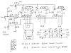
I replaced the attachment as forgot to include the Reset button in the circuit.

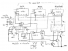
Circuit description.

Turn on Power, press Reset button, all counters are preset to Zero. Display shows 000.

Press Up button, U/D is pulled Low, the 100 nF cap starts charging towards +5 Volt.

When the cap voltage reaches the upper threshold of IC4a (after about 50 milliseconds, IC4/3 goes High and IC1 increments fro 0 tp 1. The display shows 001.

At the tenth press of the Up buitton, IC1 goes from 9 to 0 and IC2 goes from 0 to 1. Display shows 010.

If the Down button is pressed, the U/D input remains High and, after the delay, the counter decrements by 1.

The 50 ms delays have 2 functions.

1. to allow time for the contacts to settle in order to avoid contact bounce problems.

2. to ensure that, when the Up button is pressed, U/D is pulled low before the clock goes high.

I have not included the interface to the Tx. You will need two 74HC05 hex inverters for this.

I suggest you build the counter first to gain experience. Note my previous comments about the display and display driver.

I suggest that you build it on a prototyping PCB.

I don't know what is available in the US, but in Australia the electronics shops sell various types of prototyping PCBs.

The one I prefer is sold by JayCar, see the "IC Experimenter's board" www.jaycar.com.au. Catalogue number HP-9558.

They have an internet shopping site in the US www.jaycar.com.
 

Attachments

  • Decade Counter.png
    Decade Counter.png
    110.4 KB · Views: 2,569
Last edited:
I think I can follow the schematic. But I am a little confused about the switches. I know that they are creating a break between the circuit positive and the ground but I have never seen them drawn this way. I will try to get the components and set this up next week. I have some plans this weekend that will keep me out of the house most of the time.

EDIT: Couple more questions, It looks like the transistors are called out as IC4a-d. the bottom calls out IC5 as a NAND but I can't find an IC5 in the circuit. I also can't figure out where IC4b-d go in the circuit. What is the purpose of connecting both inputs of these transistors to ground?
 
Last edited:
0RESET0 said:
I think I can follow the schematic. But I am a little confused about the switches. I know that they are creating a break between the circuit positive and the ground No they do not break the +Ve. The +5V is applied via the 4.7k resistors. When a button is pressed, it connects 0V to the line (perhaps that is what you meant by "break the positive"). For example, look at the Reset button. It is normally open so the reset line (pin 11 on the IC1 ~ 3) is held high via the resistor (this is called a "pullup resistor"). When the Reset button is pressed, it applies 0V to the reset line (a Low) so the counters are reset. but I have never seen them drawn this way. The symbol I used for the push buttons represents how the button is constructed, ie. 2 contacts that are bridged when the button is pressed. I will try to get the components and set this up next week. I have some plans this weekend that will keep me out of the house most of the time.

EDIT: Couple more questions, It looks like the transistors (No, they are integrated circuits ICs) are called out as (labelled) IC4a-d. the bottom calls out IC5 (this was a mistake, it should be IC4) as a NAND but I can't find an IC5 in the circuit. I also can't figure out where IC4b-d go in the circuit. The 74HC132 contains 4 Schmitt Trigger NAND gates but you only need one, so IC4b -d are not used. What is the purpose of connecting both inputs of these transistors to ground?

The ICs I specified are CMOS devices. Unused CMOS inputs must be connected high or low, not left floating.

I suggest that you do a search of this forum for keywords such as "counter", "gate", "schmitt trigger" & "bounce suppressor".

It may help if you search for posts in which I have been involved, ie. do an advanced search with ljcox in the User Name field. This will reduce the number of hits.

See if you can understand how the circuits in some of these threads work. This will increase your knowledge of digital electronics.

If there is anything you don't understand, post a link to it and ask questions.
 
Last edited:
Alright, I have purchased everything for the circuit you drew. The main ICs are on order and will come in some time next week. Unfortunately I will be in Kentucky all next week for work.

I purchased a prototype board for the project so I will be building the circuit on there first and taking a picture to post with any questions.

I have been reading every thing that I can find on debounce and schmitt triggers. I think I have the schmitt figured out. However, most of the things that I read about it said that there is some tuning required with the resistors. I assume that the resistor values included in the schematic are known values from past experience.

I did pick up some things that were not on the list. I got three display drivers. The chips that I got are sn7447an. I also picked up a voltage regulator that puts out 5v. That item is part number LM340T-5.

Since I will be out of state next week I will not be able to check back until Friday when I get back. With any luck I will have the circuit finished over that weekend.

Sean
 
0RESET0 said:
I have been reading every thing that I can find on debounce and schmitt triggers. I think I have the schmitt figured out. However, most of the things that I read about it said that there is some tuning required with the resistors. I assume that the resistor values included in the schematic are known values from past experience.
You only need "tuning" if you want an exact delay. In your case, any delay greater than 10 millisecond will suffice since the contact bounce is usually finished within about 5 ms. So I chose a delay of about 50 ms so there is no need for "tuning". The actual delay will depend on the Schmitt threshold levels which can vary widely from one IC to another (look at the data sheet for the Schmitt) - but, since I've designed it for a typical delay of about 50 ms, then the delay will be greater than 10 ms for any IC.

0RESET0 said:
I did pick up some things that were not on the list. I got three display drivers. The chips that I got are sn7447an. I also picked up a voltage regulator that puts out 5v. That item is part number LM340T-5.

Sean
The SN7447 ICs are TTL which is (in general) not compatible with CMOS.

However, in this case, it should not be a problem since you are driving the 7447s from 74HC devices. It would not work if you tried to do the opposite, ie. drive a 74HC from a TTL device.
 
OK, all the parts are here. I have some things on the bread board trying to get a feel for how things will fit on there. I will build the circuit without the display for now, as you suggested. I have some spare LEDs laying around so I will just connect those to the output of the counters so that I can see that it is working.

Something I am unsure of is the section with the ICs and the capacitors. What is the purpose of connecting the caps to the + and gnd? it does not look like they are connected to anything else. I know it it just a representation but it is a little confusing.
 
0RESET0 said:
Something I am unsure of is the section with the ICs and the capacitors. What is the purpose of connecting the caps to the + and gnd? it does not look like they are connected to anything else. I know it it just a representation but it is a little confusing.
These are called "bypass" capacitors.

They are essential. If not included, the counters will not count correctly due to coupling via the supply line.

When a counter changes state, eg. say the counters are set to 001 and you apply a clock pulse to advance the count from 001 to 002, a pulse of current is drawn from the supply line. If there are no bypass caps, this causes the supply voltage to dip briefly. This can affect other flip flops inside the counter or in the other counters. So the result may be that the count changes actually from 001 to 048
 
OK, I get it. They work like the stiffening capacitors in a high output car stereo system.

IT WORKS!!!
I powered it up and nothing happened. I hit the reset button, nothing. I hit the up and down buttons, nothing. I then turned off the power and checked my buttons. They are DPST buttons and I had them wired wrong, basically all three buttons always on. I fixed the buttons and powered it back up, eureka, all the lights came on. I hit the reset button and they all turned off. I hit the up button and a light came on, wrong one but it came on. I fixed the order, to match what you had on the drawing, and they lit in the proper sequence.

I am so happy.

Now, How do I get the seven segment to work with the drivers I got? can I just wire it up like the data sheets say or do I need to add something to compensate for the TTL/CMOS thing?
 
Well done!
I don't know anything about high output car stereos (don't want to go deaf), but I expect you're right. The caps would do a similar function.

The 7447 can be connected to the counter directly.

Leave pins 3, 4 & 5 open (with TTL this is equivalent to a high)

Connect A to Q0, B to Q1, etc.

You'll need a common anode LED display and 7 resistors. Select the resistors for the brightness you want. I would start with 470 Ohm and change to a higher or lower value to alter the brightness if necessary.

Attached is the data sheet for the 4774.
 

Attachments

  • 7447.pdf
    126.7 KB · Views: 417
I have the drivers and display hooked up as best I can from the data sheets but have a couple questions.

Right now, when I turn it on and hit reset, I get three zeroes. When I hit the up button I get three eights. This is not how it should work. Trying to remedy the situation, I searched around. Using this I connected pin 5 to ground. This got me no zeroes but it counted up from 1 to 9 then went to gibberish. it also displayed the same thing on each digit. I needed some way to have the drivers select which digit to show. I connected the anode pins to pin 4 on the corresponding drivers. This got me a dimmer display that went blank on reset then counted from 1 to 9 on the first digit. Once I hit 10 I get a 1 in the tens place and a blank in the ones place. 11 shows up fine but 12 looks like two lower case a's and it all goes down hill from there. I can see a definite pattern so I know the counter is still working. The problem has to be in the drivers of how I am connecting them to the display.

I have all three digits using the same seven resisters with the a-g of the drivers connected to each other then running to the resisters.

I have changed things back to have the 3, 4, 5 pins open and connected the anodes back to 5v. I await you suggestions on this, I hate being so close to the pay off and not being able to get there my self.

Thanks for the help
Sean
 
0RESET0 said:
I have the drivers and display hooked up as best I can from the data sheets but have a couple questions.

Right now, when I turn it on and hit reset, I get three zeroes. When I hit the up button I get three eights. This is not how it should work. Correct! Trying to remedy the situation, I searched around. Using this I connected pin 5 to ground. This got me no zeroes Correct. Pin 5 is the Ripple Blanking input and is used to supperss leading zeros. I'll tel you how to do this later, as you may like to employ this function. eg. if the count is at 005, the display will show 5 and the tens & hundreds digits will be blank. but it counted up from 1 to 9 then went to gibberish. I don't know why this happened. See below. it also displayed the same thing on each digit. I needed some way to have the drivers select which digit to show. I connected the anode pins to pin 4 on the corresponding drivers. Pin 4 is the Ripple Blanking output. You don't need to use it at this stage. This got me a dimmer display that went blank on reset then counted from 1 to 9 on the first digit. Once I hit 10 I get a 1 in the tens place and a blank in the ones place (I presume this is due to the Ripple Blanking. Connect RBI to +5V or leave it open) 11 shows up fine but 12 looks like two lower case a's (I don't understand why this is happening) and it all goes down hill from there. I can see a definite pattern so I know the counter is still working. The problem has to be in the drivers of how I am connecting them to the display. Have you studied the Function Table in the 4774 data sheet? This shows how it is supposed to operate.

I have all three digits using the same seven resisters with the a-g of the drivers connected to each other then running to the resisters. This does not make sense. This may be the cause of your problems! You need 7 resistors for each display as implied in my circuit diagram.

I have changed things back to have the 3, 4, 5 pins open and connected the anodes back to 5v. I await you suggestions on this, I hate being so close to the pay off and not being able to get there my self.

Thanks for the help
Sean

You're welcome.

If I understand what you mean by the "7 resistor" comment above, then this is the cause your problems. But I don't see how you could connect 7 resistors when you have 3 displays & 3 display drivers. You need 21 resistors.

Do you have LEDs connected to the Q outputs of the counters? These will show you the binary state of the counters so you know what the counters are doing.
 
ljcox said:
You're welcome.

If I understand what you mean by the "7 resistor" comment above, then this is the cause your problems. But I don't see how you could connect 7 resistors when you have 3 displays not three displays, one display with three digits & 3 display drivers. You need 21 resistors.

If you refer back to the display data sheet that I linked to a while ago, you will see that there are only one set of a-g pins on the display. There are three pins for the common anodes that are digit selectors. I assumed that there was something inside the display that used the seven and three to make the 21. I will read thru the data sheets again and see if there is something that I missed. There has to be some out put on the driver that I can connect to tone of the common anode pins so that the output from that driver goes to a certain digit. I guess I can go out and pick up three separate displays but I like the space savings of only needing 7 resisters.
 
Last edited:
0RESET0 said:
If you refer back to the display data sheet that I linked to a while ago I could not see what link you are referring to at a quick scan. I think from memory, you're talking about the 4553 three digit BCD counter. This is not suitable for your application since you need binary outputs to drive the Tx , you will see that there are only one set of a-g pins on the display. There are three pins for the common anodes that are digit selectors. This because the IC does MULTIPLEXING which means that you only need 7 resistors. But you can't interface this counter to your Tx. I assumed that there was something inside the display that used the seven and three to make the 21. I will read thru the data sheets again and see if there is something that I missed. There has to be some out put on the driver that I can connect to one of the common anode pins so that the output from that driver goes to a certain digit. I guess I can go out and pick up three separate displays but I like the space savings of only needing 7 resisters.

I'm confused as to what you want.

Do you want only one display and switch to select which digit you want to read? In other words, it would be a 3 position switch that selects the Hundreds, Tens or Units digit for display. This would only need 7 resistors.

If so, this is possible in theory, I would have to think it through and draw a circuit. But I need to know exactly what you want.
 
Here is the data sheet again.

I was not referring to the counter chip. Like I said, the display I have has three digits on it but only one set of pins for the a-g from the drivers. This is why I connected all three displays to the same seven resisters. I assumed that the three separate pins for the anodes of the three different digits was somehow working to separate the incoming signal but it does not make any sense to me.
I hope you know what to look for can take a look at the data sheet for the display and tell me how I am supposed to connect three drivers to it and have it work properly.
 
Now I understand. I had downloaded the display data sheet but did not study it in detail.

The display is meant for multiplexing.

In order to do this, you will need another IC (a flip flop) configured as a Modulo 3 counter, 3 transistors and 3 (possibly 6) resistors.

You will be able to employ the currently unused gates in IC4 as a part of the system.

I'll design it for you later and post tonight.

EDIT
Here is a multiplexer to drive your display.

You're lucky that the 7447 has open collector outputs. This allows you to connect the outputs in parallel. Some 7 seg drivers don't have o/c outputs.

IC4b operates as an oscillator. If R11 = 100k and C1 = 100 nF, then it will oscillate at about 50 Hz. The frequency is not critical, it just has to be high enough so that the display does not flicker.

50 Hz implies a cycle time of 20 milliseconds (ms).

So each display is turned on for 20 ms in sequence, ie. only one display is "energised" at any time, but it is so fast that they appear to be all on simultaneously.

IC5 is configured as a Modulo 3 counter. The count sequence is 00, 01, 10, 00, etc.

When YX = 00, the output of IC4c is low so T1 is turned on and the output of IC4d is high therefore the units driver is enabled (high on BI) so the units digit is "energised".

When YX = 01, the Tens driver is enabled and T2 is on so the tens digit is "energised".

When YX = 10, the Hundreds driver is enabled and T3 is on so the hundreds digit is "energised".

The transistors T1 ~ T3 can be any PNP transistor such as the BC327, BC328, BC556, BC557, etc.

Resistors R1 ~ R7 need to be lower in value to compensate for the multiplexing. I suggest you test it first with whatever resistors you have installed, but the brightness will be low.

Once you have it working, install resistors of about one third value, eg. if you currently have 470 Ohm ones (and if the brightness was OK before building the multiplexer), replace them with 150 Ohm.

IC5 is a 74HC73. Let me know if you can't buy one of these and I'll suggest alternatives.

Any questions? just ask.
 

Attachments

  • Scan 4.png
    Scan 4.png
    126.4 KB · Views: 449
Last edited:
Sweet, I will try to get my hands on the new parts. Would it be easier to just get three new displays, single digit type? I can probably get them at the local Radio Shack. This would mean I have to use 21 resistors but I bought that many any way.

I have some spare parts like capacitors and transistors. Is there a way to identify them to see if I can reuse them?

Sean
 
0RESET0 said:
Sweet, I will try to get my hands on the new parts. Would it be easier to just get three new displays, single digit type?
Yes, it would, but it is your choice.
I can probably get them at the local Radio Shack. This would mean I have to use 21 resistors but I bought that many any way.

I don't know what your Radio Shack sells, but I can buy resistor networks very cheaply at Semtronics. Semtronics sell electronic parts to industry.
They come in 2 versions, SIL & DIL. The DIL ones look like an IC. This would make it smaller for you.

I have some spare parts like capacitors and transistors. Is there a way to identify them to see if I can reuse them?

Sean
Do the transistors have any numbers on them? What do they look like?

Do you have a multimeter that has a transistor test function? If so, use it to determine whether the transistors are PNP or NPN and to identify their connections.

If not, it can be done with a multimeter set to the resistance function.
 
Last edited:
I really like the idea of the resistor networks. Can you give me a part number for a dual in line type? I will use the regular resistors for now so that I can play with the value to get the brightness I want.

I am going to just order three separate displays, so I won't need the other stuff any more right? I will try to find some resistor networks while I am ordering the displays.

I order my stuff thru Mouser electronics at www.mouser.com
ever heard of them?

I have a question about the interface with the computer. I know I am getting ahead of my self. Would it be possible to make is so that I can use the remote separately by pushing the buttons that I am using in this circuit. Then have it so that I can plug it into the parallel port and just have the "computer push the buttons"?

EDIT:
I can't get single displays from Mouser and I didn't find a resistor network that had the proper resistance. To make matters worse, if I get displays that have a different forward voltage I will not be able to use the resistors that I bought already.
So, Since I did not have a chance to stop at Radio Shack today, I will stop there tomorrow and see what they have for displays.
 
Last edited:
0RESET0 said:
I really like the idea of the resistor networks. Can you give me a part number for a dual in line type? See the photo attached and comments below. I will use the regular resistors for now so that I can play with the value to get the brightness I want.

I am going to just order three separate displays, so I won't need the other stuff any more right? Correct I will try to find some resistor networks while I am ordering the displays.

I order my stuff thru Mouser electronics at www.mouser.com
ever heard of them? Yes, I've heard of them through this forum.

I have a question about the interface with the computer. I know I am getting ahead of my self. Would it be possible to make is so that I can use the remote separately by pushing the buttons that I am using in this circuit. Then have it so that I can plug it into the parallel port and just have the "computer push the buttons"? Yes.
EDIT:
I can't get single displays from Mouser and I didn't find a resistor network that had the proper resistance. To make matters worse, if I get displays that have a different forward voltage I will not be able to use the resistors that I bought already. I don't know what they cost in the US, but they are cheap in Oz.
So, Since I did not have a chance to stop at Radio Shack today, I will stop there tomorrow and see what they have for displays.
The photo shows some SIL resistor networks that have a common - the dot of the LHS. You can buy others that have individual resistors in them.

The DIL is a 330 Ohm one. You can see the number on the tube that they came in.

The Australian company JayCar have a good range of parts (but not resistor networks) a web site and mail order outlet in the US/Canada. See www.jaycar.com, email techstore@jaycar.com, US phone number 1800 784 0263.
 

Attachments

  • res net 001.jpg
    res net 001.jpg
    67.9 KB · Views: 232
Last edited:
Status
Not open for further replies.

New Articles From Microcontroller Tips

Back
Top