Continue to Site

Welcome to our site!

Electro Tech is an online community (with over 170,000 members) who enjoy talking about and building electronic circuits, projects and gadgets. To participate you need to register. Registration is free. Click here to register now.

  • Welcome to our site! Electro Tech is an online community (with over 170,000 members) who enjoy talking about and building electronic circuits, projects and gadgets. To participate you need to register. Registration is free. Click here to register now.

Controlling A robot using Cheap Rc car controller. (SFDP)

Status
Not open for further replies.

Mr_Max

Member
HI every one

I Want to use A cheap rc car (transmitter & reciver) to control A Small robot

the problem is due to high power source i want to use(gp 7.2v 1600 mA battery)

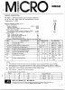
which the two H-bridge circuits , the reciver chip shown in the circuit below aren't able to

handle that much current

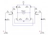
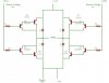
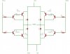
so how to make the reciver circuit only control more powerfull h-bridge ( a tip's 102 & 107 or

mosfet transistors) provided that each circuit uses it own source of power

reciver circuit operating at 9v (6 aa batteries) 600 ma & a tip's or mosfet H-bridge operating at

7.2v 1600 ma

the reason that i want seperate sourcres of power is that im afraid that the reciver chip

aren't able to handle that much current (it mighty get fried)

should i use the ouput of the rc reciver h-bridge to control the tip's/mosefet h-bridge

if this is possible how ? i'm using a Mabuchi motor for throttle


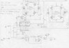
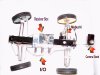
included the reciver circuit,
 

Attachments

  • circuit-diagram_203.jpg
    circuit-diagram_203.jpg
    114 KB · Views: 4,423
Re: Any one Kind enough to help

Mr_Max said:
here is the h-bridge circuit i want to merge with the radio control reciver

http://www.mcmanis.com/chuck/robotics/tutorial/h-bridge/bjt-circuit.html

please tell me which wires to connect & components that needs

replacement.

It looks difficult to do?, the H-bridge circuit at the link above is quite unusual, it requires manipulation of three pins to control it. You would need to design a logic system to convert between the two systems, or find a more 'normal' H-bridge design.
 
just connect the Enable pin to vcc (or GND whatever it need) and dont turn any attention to it. then connect the H-Bridge and the way you go

but i cant understand why cant you just change the transistors in the original schematic.
 
Thanks alot for your interest

Thanks alot for your interest in my topic


yes the BJT circuit is confusing ! but this is what i found.


Any H-bridge circuit that can handle the 1600ma current & the mabuchi
motor would be fine .

what is your opinion :- [NEC] 2sd401a & 2sb546 Based h-bridge

here is the datasheet

& the circuit

if any one knows a beter h-bridge that works please let me know.

& please i wish to know if the idea of 2 seperate sources of power would work or not? 7.2v to external h-bridge & 9v to receiver circuit

this circuit is my trial i don't know if it works if any one cant tell me if it does?

the idea is that by connecting the output of the reciever h-bridge (2 wires red & black)

to (a) & (b) so when i press for ex. the (throttle) forward button say point (A) would be +9v

& Point (B) would be -9v so the diodes allow the +9v & block the -9v & vice versa

thus simulating the 0 1 1 0

as i said it is only a trial i don't have much experience about Electronics
 

Attachments

  • alternative_circuit.jpg
    alternative_circuit.jpg
    19.4 KB · Views: 2,047
  • 2sd401.pdf
    111 KB · Views: 924
  • 2sd401a.pdf
    615.2 KB · Views: 682
I can't just change the transistors in the original schematic

because i'm afraid that the 1600ma current might fry the reciver chip

if a short happens in the circuit ?

but if you see it possilble let me know that would be great

what do you think about the NEC Transistors that are able to hanldle a 3A

current I have bought them already but i didn't solder it yet!

could these transistors be used to make H-bridge of any form
 
I'm sorry for that mistake in the NEC H-bridge circuit the upper & lower transistors were reversed ,i hope that this one is correct

please tell me if there is any thing wrong with this circuit & how to overcome it?

to clarify :

I want your help to find the simplest h-bridge design that would do the job . no (PWM) no
(differential Steering)

I'm using this R/c transmitter & reciever circuits to control a small robot i made.

For throttle i'm using A (Mabuchi Motor) & for steering i'm using a small (powerfull) old

recorder DC motor both motors are geared.

it's a 2WD robot (2 wheels at the back 11cm radius) connected to a gearbox thorough (4 Rods & 8 joints)

& for steering (2 free wheels 11cm radius) connected together by (2 Rods 4 joints) & to the steering motor (a real car steering type)

the reason i built this robot is to simulate a real car or truck mechanism .

as shown in the provided picture there 4 shocks & the movement is transferd to the back wheels

through 2 axles so if there are small rocks in the way these shocks works great providing

A travel Radius up to 6cm (rear shocks) 4cm (front shocks)


note: the old h-bridge transistors data sheets S8550,s8050 & s9014 are included
i hope this could help!

i'm sorry but i have so many things in mind with regard to this topic ,is it possible to

use the s8550 & s8050 to drive the (NEC) D401 & B546 H-bridge
 

Attachments

  • correct_alt-circuit.jpg
    correct_alt-circuit.jpg
    20.6 KB · Views: 4,984
  • 3d_views.jpg
    3d_views.jpg
    146.6 KB · Views: 1,601
  • mr_max_robot.jpg
    mr_max_robot.jpg
    184.8 KB · Views: 2,406
data sheets

s8550

s8050

s9014
 

Attachments

  • datasheets8050.pdf
    69.5 KB · Views: 485
  • datasheets8550.pdf
    86.3 KB · Views: 505
  • datasheets9014.pdf
    38.6 KB · Views: 594
Rx-2B datasheet

I will just keep replying to my self :!: :?: :?
 

Attachments

  • rx-2b.pdf
    178.5 KB · Views: 762
  • ksd882.pdf
    48.7 KB · Views: 499
the chip suply voltage is 5V max. you cant connect it to 7.2V ever! put a low dropout regulator betwean. for the transistors use the ones stated in the RX.-2B data on use relays driven by transistors given in the datasheet. relays can take biger currents than transistors. how to connect a relay to the transistor i hear you say? use the internet. it is full of all kinds of examples and theory articles. learn the simple principles of electonics. it aint that hard you know.
 
Just to confirm if i just replaced the old transistors with the D882 , b772 & put a Low Dropout Linear Regulator

i could attach the 7.2 gp battery & have no fears of melting the transistors or the rx-2b chip? :idea:

one more thing in the chip datasheet page 10 the supply voltage colud be 9v or 12v but there is a resistor that have to be changed

9v 220ohm
12v 330ohm

would this FAN1086 Low Dropout Linear Regulator be fine?
 

Attachments

  • fan1086.pdf
    172.2 KB · Views: 647
Hi
Your original circuit should work fine. The tip107/102 darlingtons are rated for 8 amps, so as long as your motor doesnt draw more than that (and I doubt that it does), you should be fine. You dont have to worry about "frying" your chip because the motor current doesnt go through it. The chip just sends a low current control signal to the darlingtons - THEY handle all the motor current. Your 1600ma battery may be the only limiting factor in this setup.
PS - Thats a cool little car!
 
Some topics get the most attention while others sink

THE final Bot 8)

with some paint ,a stand for a small digital camera
& the ability to mount a video sender hooked to the camera.

I hope you like it

thanks for all people who gave me advice & hints in this

s project :wink:
 

Attachments

  • robot_end2.jpg
    robot_end2.jpg
    144.8 KB · Views: 924
  • robot_end.jpg
    robot_end.jpg
    161.6 KB · Views: 1,026
good job

I've been working my robot.You robot way better than my robot. see here is robot. Soon will be a combat robotrobo1.jpg
 
Status
Not open for further replies.

Latest threads

New Articles From Microcontroller Tips

Back
Top