Continue to Site
Follow along with the video below to see how to install our site as a web app on your home screen.
Note: This feature may not be available in some browsers.
")
If you convert this into a real and an imaginary component, the real part is called the watts, and the imaginary part is called the vars (var = volt amp reactive).
You may also encounter a term called the power factor. The power factor is the cosine of the current angle subtracted from the voltage angle. A power factor of 1 means that the voltage and current are perfectly in phase. The power company likes to have a power factor of 1 on their lines, since this makes the transmission of power more efficient. Since most household loads are slightly inductive (due to motors in hair dryers, vacuum cleaners, dishwashers, etc), the power company adds capacitors to the line to compensate for the inductance.
These three types of power are trigonometrically related to one another. In a right triangle, P = adjacent length, Q = opposite length, and S = hypotenuse length. The opposite angle is equal to the circuit's impedance (Z) phase angle.
Hi
Re: Power factor correction
Q1:
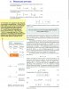
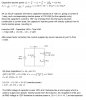
Please have a look on these circuits. Suppose that circuit #3 is being used. If an ammeter is connected to the circuit, it will read 1.410A and we can erroneously conclude that power being delivered to the load is 169.256W but that is not the case. On the other hand, a wattmeter would give us true value of 119.365W because it only reads true or real power and not the reactive power which keeps bouncing back and forth between the source and load without doing any real work.)
Power companies always encourage power factor of unity because it create issues on their side such as it results in more I²R losses. )
Power factor correction method could be employed to make the power factor unity. The power factor correction method makes a load behave like a resistive load instead of a reactive load. If power correction method is applied to circuit #3 then it will ideally behave like 60Ω resistive load to the 120V source and still delivering same 'real' power of 119.365W.
Do I have it correct so far?
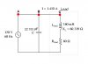
Let's see how power factor correction method is applied to circuit #3. Please have a look here. Do I have it correct?
In the example we saw that after power factor correction the current supplied by source reduces from 1.410A to just 1A. As the supply now just have to supply only 1A therefore firstly I²R losses are reduced and secondly now the unused 0.410A could be used by the source for some other load. Do you agree with this?
I believe that the current between nodes "A" and "B" is 1A but the current between nodes "B" and "C" is still 1.410A. I mean that if an ammeter is connected between the nodes "B" and "C", it will read 1.410A. Do you agree with me?
In real world most reactive loads are inductive in nature such as motors and transformers. Let's see how a power factor correction method works from a layman's viewpoint. Please have a look here.
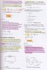
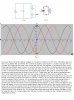
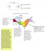
The power factor correction method is based on concept of LC tank circuit. For more information about LC tank circuit, please refer to the links. The currents of capacitor and inductor in LC tank circuit are 180° out of phase. But what does this mean when we say that they are 180 degrees out of phase with each other? There might be different ways to look at it. Let's try this one. We will focus on the waveforms at the instant when they are crossing y-axis in Fig 1; notice the dots. Also have a look on Fig 2. The inductor pushes the current in counterclockwise direction and at the same time capacitor also 'pulls' or 'sucks' the current counterclockwise toward itself (thinking in view of Fig 2). These 'push' and 'pull' actions complement each other. Under ideal conditions this 'push' and 'pull' can go on forever. If there were no capacitor then inductor current would always lag the source voltage by 90 degrees assuming no load. In such a case, the source would need to reverse the direction of inductor current on its own and this requires energy which is stored in magnetic field of inductor. It's like stopping a moving car and it will take some energy to stop it due to its momentum before it can go in the opposite direction. In presence of a capacitor this job of reversing the direction of inductor current is performed by the capacitor. In other words, the capacitor acts like a local supply which is only there to supply/absorb reactive power to/from the inductor, and the main supply can only focus on supply current to the resistive load. Or, we can think that complementary action of capacitor and inductor takes away the affect of reactive power from the circuit and for the supply the load overall behaves like a resistive one. Do not forget that we are assuming that the system has been running for some time and it is in steady state. Also note that in actual circuit there is only a single current and no independent currents.
Do you think that I have it right to some degree?
Thank you.
Regards
PG
No, you calculated in the next question that a PF of one would make the circuit look like a 120 ohm resistor.
Thanks a lot for helping me with the queries, Ratch.
Now I look at it again carefully, I feel that I don't really understand it.
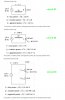
This is the calculation which was made. We have a 60.319Ω inductor and 60Ω resistor in series and it gives total series resistance of 120.319Ω. As was calculated the current supplied by AC source is almost 1A and 0.410A is supplied by the capacitor. This is how I was thinking previously. I was under the impression that inductor is totally 'powered up' by the capacitor and the AC source is only concerned about supplying power to the resistive load. In other words, I was treating the interaction of capacitor and inductor in a way as if they are really absent from the supply's perspective and they both constitute an independent system of their own. But Ohm's law fails, i.e. 1^2*60 (power dropped across load)≠120*1 (power generated by supply), where "60" is resistance of load, "1" is current supplied by the source and "120" is RMS voltage of the supply. Total power generated by the source is 120W but only 60W is dropped across the resistor which means the remaining 60W is dropped across the inductor. What are those 60W doing in the inductor?
Please also note that I do understand that overall resistance of the system is 120Ω as is calculated here in detail.
Where am I going wrong? Could you please guide me? Thanks
Regards
PG
Thank you, JimB, Ratch.
Mathematically, I understand it but conceptually I'm somewhat confused.
The 120V supply is supplying 1A which means it's outputting 120W. The power dissipated by resistive load is also 120W because the current passing thru it is 1.41A.
The current supplied by power supply is 1A but the current passing thru load is 1.41A. Where does extra 0.41A come from? I believe that it comes as a result of power/energy swap between L and C because this power/energy has to travel thru the load and power is product of voltage and current. The voltage being dropped across load is 84.6V. I'm having difficulty visualizing how all this is taking place. Could you please guide me? I have also attached Multisim13 circuit. Thanks.
Regards
PG