Continue to Site

Welcome to our site!

Electro Tech is an online community (with over 170,000 members) who enjoy talking about and building electronic circuits, projects and gadgets. To participate you need to register. Registration is free. Click here to register now.

  • Welcome to our site! Electro Tech is an online community (with over 170,000 members) who enjoy talking about and building electronic circuits, projects and gadgets. To participate you need to register. Registration is free. Click here to register now.

COMPLEX SOUND CHIP 76477

Any interest in boards

  • Sdip adapter board to adapt from 1.77 pitch to 2.54 pitch

    Votes: 0 0.0%
  • A 3 "x 4" aprox PC board for a complex sound circuit using a 76477 chip and a 555 chip

    Votes: 0 0.0%

  • Total voters
    0
Status
Not open for further replies.
That "look at it" part? This is what you'd see.

View attachment 98162

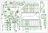
Typical of a poor resolution scan, now followed by a zooming attempt which just puts in evidence the pixels.

As already posted somewhere before in this thread, to all surveyors working with me (they have to send (by email), documents signed upon completion of their survey, properly scanned; I request to open them in their own PCs, and check by themselves how they look.

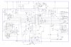
BTW, I never scan anything I generate in Corel Draw; I "print" it in .pdf and have no problems at all. Look here below.
 

Attachments

  • PS2 protocol timing.pdf
    22.3 KB · Views: 192
Printing to pdf is an excellent way to transfer drawings. Plenty of free tools exist to do this, like PrimoPDF, and it's as easy as printing a file.

A PDF sometimes takes an extra click compared to viewing an image in a forum, but they definitely give you the edge in resolution.
 
schematic jp.jpg
well here is a 300 DPI jpeg
 

Attachments

  • jpeg of board.jpg
    jpeg of board.jpg
    271.8 KB · Views: 165
Sigh. You posted a small piece of the schematic. Why? It's not useful. Look at it and delete it if it's crap. Why subject people to looking at your errors?
 
lets try again. I reduced in Diotrace at 300 dpi
 

Attachments

  • jpeg rev 4.jpg
    jpeg rev 4.jpg
    389 KB · Views: 163
I looked at the preamp and saw that the electret mic has R24 with a resistance much too high powering it. An electret mic draws 0.5mA and the 100k resistor for R24 creates a voltage drop of 0.5mA x 100k= 50V! Then the mic will do almost nothing since the supply is only 5V. R24 should be 2V/0.5mA = 4k ohms (use 3.9k).

I simulated the mic preamp because I suspected that it is biased wrong. Its bias resistor is much too small so the transistor is almost saturated. The input capacitor was 0.1uF which passed no low frequencies but now it is 1uF which is better.
I simulated it and changed its 100k biasing resistor to 1.8M then it works much better. My simulation has a 2.5k resistor as the impedance of the electret mic.
 

Attachments

  • MrDEB preamp.png
    MrDEB preamp.png
    41 KB · Views: 141
Thanks audioguru.
the preamp circuit came off a data sheet somewhere concerning this circuit. I found two similar circuits.One used a crystal mic with a 1.5M bias resistor.
Want to locate both and hopefully simulate as well
The preamp circuit allows the user to insert their voice intermixed with the sound generated by the chip.
 
This could be a fantastic project, especially if the 20-some switches and 10 or so pots are laid out in a logical sequence so the operation makes sense (i.e., related controls are grouped together). This will require a large panel for a workable arrangement.

If I were doing it, I would want a large circuit board for all the controls. Soldering pigtails to switches and pots is something I hate - reliable results require a lot of effort. If I used pigtails, I would use separate 2 or 3 pin cables (as needed) to connectors on a circuit board. MrDEB's idea of a ribbon cable from a dual-row header fanned out to different switches and pots has never worked well for me; the conductors are too fine and won't take much abuse while getting everything wired up.

I look forward to seeing LGM's simplifications...and later his microcontroller interface <g>
hod did you know I was sticking a micro on? I was thinking cap touch and electronic switching, save a fair bit of money
 
Just i good guess ;) Everything is better with a micro!

You'd need a bunch of analog switches for the caps, but digi-pots would be a huge simplification while providing more control.

Nice idea!

A quick count would be about 51 switch positions and 7 sliders to duplicate what's there now. A fairly complex cap touch design but the complexity is all in the circuit board design. Duplicating it would be a breeze.
 
Last edited:
Am thinking about adding some visiual effects such as multi collored LEDs combined with several band-pass filters.
 
Just i good guess ;) Everything is better with a micro!

You'd need a bunch of analog switches for the caps, but digi-pots would be a huge simplification while providing more control.

Nice idea!

A quick count would be about 51 switch positions and 7 sliders to duplicate what's there now. A fairly complex cap touch design but the complexity is all in the circuit board design. Duplicating it would be a breeze.
I got a different idea to didgi pots ;), also I been thinking about the make before break problem, if the switch position was on a pot and the pot went to a ADC then the switch chip could be controlled by a couple of normal pots, leave enough gap between the voltages of say 250mV or 125mV . 'switch' that is on is indicated by a led. i am not 100% sure yet the chip needs to get here and I have stuff to get out the way. also exams Easter so only get 2 hours a day of 'fun' the rest is pure work :oops: (sort of). Although seems a bit untruthful to call it work when you love doing it lol
 
heres thought, combine a thermin type circuit with the 76477
Wouldnt work two different principles, the chip makes the noise and so does a theramin, the two are very unlikely to go well together but feel free to try it out. Be warned theramin seem like a good idea but the one I built 3 years ago was sort of meh after 2 mins
 
jpeg of sch rev4.jpg
cleaned up schematic and added the cap on pin 5 of the 555 to grd. Also added the tie points markings (all them little black dots) that coincide with the PCboard as to which panel component connects to the PCboard.
changed the cap and resistor values on the pre amp mic input.
 
Your schematic looks much better. It gets larger when I click on it.
I do not knowhow to upload the LTspice IV file of your mic preamp so here are its setting:
 

Attachments

  • mic preamp sim.png
    mic preamp sim.png
    29 KB · Views: 146
Thanks audio. I located the pre amp schematics and going to research.
thinking of maybe adding several band pass filters but ?? for LED flare.
 
well I got something not right. Trying to duplicate what Audi came up with in LT spice
 

Attachments

  • lt spice.jpg
    lt spice.jpg
    162.4 KB · Views: 158
Status
Not open for further replies.

Latest threads

New Articles From Microcontroller Tips

Back
Top