Electro Tech is an online community (with over 170,000 members) who enjoy talking about and building electronic circuits, projects and gadgets. To participate you need to register. Registration is free. Click here to register now.
Welcome to our site! Electro Tech is an online community (with over 170,000 members) who enjoy talking about and building electronic circuits, projects and gadgets. To participate you need to register. Registration is free. Click here to register now.
Just hard solder it in the board, I personally think its a good little chip for what it does and the retro sounds would cool. I *might* get one to play with depending on what they cost
been re thinking how to mount all the caps and resistors that connect to the rotary switches. At present I have a design where the main board has 2- IDC 14 pin connectors but still need to hard wire each switch so maybe just mounting all the resistors and caps on main board is the better option.??
Will try getting a pdf as suggested
Im surprised you were able to find these chips. The part number looked real familiar to me, so today I google one of the numbers, and I recognized the block diagram. I had bought one of those chips back in the 70's when I was a teenager. In fact I still have the part in my IC tray (Boy am I a packrat). If I recall, it was a pretty fun part to play with, of course at the time, I had no idea what all the blocks did, and only figured out what they did thru experimentation (Before internet, we were on our own).
Well been laying out different boards and trying to cut down on the parts count as well as getting a readable schematic to post. I recall having to use bitmap but??
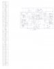
here is where I am at. Lets see if this is readable
You might go back and read the 5 forum pages where people went into excruiating detail in an attempt to help you post a readable schematic. I doubt anyone will try again to guide you through the process. BTW, the schematic you posted is not readable.
I attempted to searc for the thread about posting a readable schematic and unable to find it. Tried several search terms but no success.
I do recall using a bitmap and infa view.
Going to try several options. Thanks for input
well here I increased the jpeg to 600 DPI lets see if this is any better.
In preview it looks pretty good but I didn't get all of the schematic Oups,
I used a generic pattern for all the switches as they are all SPDT except the mono pushbutton but they are clearly marked.
Still looks like too many parts but?? I have the time after I order some boards.
Reasonably clear instructions, with one recommendation that shouldn't need repeating again:
"When you make a post, look at the file once it's posted. If YOU can't read it easily, delete it and save it in a larger size. If you can't read it, don't expect anybody else to make the effort to do so."
This picture is from you latest schematic. Either the pins on the chip are labeled in Chinese or your schematic isn't readable.
One more hint: Get rid of the crap you don't need. I have no idea what the column of stuff down the left side of what you posted is, but it's not essential to viewing the schematic. Crop your images to the essential areas.
The very first one you posted in this thread I could read, I said at the time that JP started talking about PDF's etc DO NOT DO IT!! You had it working when you first posted in this thread, golden rule of life if it aint broke dont fix it (unless your bored or me). So go back to what you did with the first schematic in the first post or two in this thread. We can help you draw a decent one once we can read it.
Dont worry about switches etc, first job get the drawing readable, second job we work on making the schematic easy to understand. THEN we can start designing and adjusting circuits, this way will get your project done fast, ANY other way will result in a...........................
This site uses cookies to help personalise content, tailor your experience and to keep you logged in if you register.
By continuing to use this site, you are consenting to our use of cookies.

")