Continue to Site

Welcome to our site!

Electro Tech is an online community (with over 170,000 members) who enjoy talking about and building electronic circuits, projects and gadgets. To participate you need to register. Registration is free. Click here to register now.

  • Welcome to our site! Electro Tech is an online community (with over 170,000 members) who enjoy talking about and building electronic circuits, projects and gadgets. To participate you need to register. Registration is free. Click here to register now.

Compare Arduino ADC to 16 bit ADC Chip

Status
Not open for further replies.

MrAl

Well-Known Member
Most Helpful Member
Hello there,

Here is a quick comparison of the ADC in the Atmega 328 chip in an Arduino Uno and a 16 bit ADC separate chip. It would be nice to hear about other people's uses too, as to any comparisons they performed.

The Uno uses the +5v reference available on the board, which is not as stable as the 16 bit ADC internal reference, so the difference in readings is often more off by about 3 or 4 millivolts, and as high as 5 millivolts. The only calibration for the 328 chip ADC is done by measuring the +5v supply and using that measurement as a factor in the conversion from the ADC code to the voltage displayed.
There is no calibration for the 16 bit ADC, which is found to be very close to a measurement with an expensive meter, although some calibration would help there too.

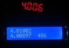
The attachment shows three readings, although the top 'red' display should really be ignored because that was taken with the ground lead on a different point in the circuit.
The top reading in the blue display is the 16 bit ADC, and the bottom reading is the 328 chip ADC, and the number to the right on the bottom in the blue display is just the sample count.

The conclusion was that the 328 chip differs from the 16 bit ADC by up to 5 millivolts, but the power supply on the Arduino board was found to vary, so a better reference voltage would probably help there. In any case the +5v has to be measured in order to set the factor in the code correctly, or at least close. If a different reference is used that would have to be measured.
 

Attachments

  • ADC_Compare-1.jpg
    ADC_Compare-1.jpg
    56.4 KB · Views: 435
To really compare, it would be nice to use same reference for both converters. I am sure the vref is the big factor in your results. Can the Arduino use an ext vref?
 
To really compare, it would be nice to use same reference for both converters. I am sure the vref is the big factor in your results. Can the Arduino use an ext vref?
That's what they use. It's a cap and a 10 resistor to vdd the supply keeps the cap at vdd and the cap feeds the inrush to vref it works really good I did some over samples to get 16 bit wasn't bad better then what I could get with a pic and swordfish basic adc libaray. But it also has a 1.1 ref it can read vdd real voltage.
 
Hi,

Yes, but using the same for both is not possible right now because the 16 bit chip has a built in reference without access to any of it's pins.

I tried the 1.1v reference internal to the 328P chip. It's always partly a matter of calibration anyway though. Using the 1.1v reference i'd have to connect two resistors to the ADC input so i can read up to 5 volts. They would not be exact either, so i'd have to do some sort of calibration anyway i guess.
Also, i could not find a temperature spec on the 1.1v ref, although it is bandgap.
The initial accuracy of the 1.1v ref is also not very good, so it has to be measured with each chip in order to use it effectively.

The readings without resistors and calculating the code factor when using the 1.1v reference, the readings come out within about 2mv of each other.

Mike you are right though, using the same reference would be the only way to really know for sure. That would mean both factors would be the same so any variation is due to the chip itself.

What i could test though is the variation over the full input range, like 0 to 1v or 0 to 5v or whatever the reference is set to.

I am wondering how these chips compare to the Microchip chips as i have always gotten good results with those chips.
 
I've not looked at the adc libaray of the ardunio it works fine for what I do. The adc can do some cool stuff on the ardunio like read stunt resistor with to adc pins
 
Hi,

Did you mean a shunt resistor?

Wait maybe i can check the accuracy to some degree.
If one voltage is say 4.9000 and the other 5.1000 then i know i have to use those two numbers as factors in the conversion to float or BCD. Using the measured values should give comparative results.
 
I'm on my phone washing clothes today at laundormat lol its a shunt you can hook one up as long as the voltage aross it its over five volt it can read it. Pretty neat. If your using the libaray that's not a good comparison
 
Hi,

What library?
 
Hi,

Oh ok, so you mean the libraries that come with the IDE.

So what is wrong with using them?
 
Hi,

I thought that you thought that something might be wrong with the lib, not that you were asking if there was anything wrong. I seriously doubt there is anything wrong with that, i think it's all hardware from here.

There is another noise issue though, but that is hardware. A cap on the Aref pin is supposed to help with the noise in the ADC for the 328 chip.
 
A much better comparison would result from sweeping the input voltage slowly to both ADC converters and reading them simultaneously, and logging both ADC values at many points over their range. By plotting one ADC reading vs the other, you can get a pretty good gain/offset plot over the entire 0 to 5V range.

Even better, use a third method to actually measure the real voltage at each test point. Best I could do would be to use a precision 10-turn pot connected to a stable lab supply, and then read the resulting test voltage on my 4 1/2 digit Fluke DMM. Use those readings as the x-axis of a plot, and plot both ADC readings on the y-axis of the same plot... That would show non-linearities, discontinuities, slope errors, offset errors...
 
Hi Mike,

Very good idea. I was using a 10 turn pot but a controlled sweep would be much better. I dont even need every single nano volt either, just maybe several steps, so a stepped wave would be good too i think, giving time for each ADC to settle.

I want to use this for some general purpose instrumentation so i want to know the limits. I dont even think i tested the PIC ADC's this extensively but i never had a problem so i didnt worry about it. Now i wish to look a little closer and make sure what i am reading is what is really there :)

I'll throw a little circuit together for the stepped wave and hopefully have some results by later today or tomorrow morning.

I hope you dont mind, but i have to give your post at least a 'like' for that suggestion :)
 
Comparing an 8-bit microcontroller ADC to a dedicated 16-bit ADC chip. Not fair!
 
Comparing an 8-bit microcontroller ADC to a dedicated 16-bit ADC chip. Not fair!
Actually the ATmega 328 has a 10-bit DAC.
 
Actually the ATmega 328 has a 10-bit DAC.
Actually the ATmega 328 does not have a DAC.
Sorry for the sarcasm. Anyway comparing 10-bit ADC on an 8-bit microcontroller to a dedicated 16-bit ADC chip is not fair. And reference voltage is the key to precision. Temperature controlled reference voltage.. what is it called.. "ovenized"?
 
You all are getting funny a fluke at best is going to be the same maybe 5% more like 3% if it's calibrated. And I'm with MrT it's not fair a test 16 ADC and 10 bit AVR.
And my point about the library is. Are you using it you said yes. Ok how you using it because it can overy sample to give better reading it's really good. And the cap is not just for noise and it's not even made right on the arduino there should be a cap 100nF too ground and the AVCC pin and 10uH to VDD this supplies power to the the noise canceler inside the atmega.
Features Of the Atmega ADC
• 10-bit Resolution
• 0.5 LSB Integral Non-linearity
• ± 2 LSB Absolute Accuracy
• 13 - 260μs Conversion Time
• Up to 76.9kSPS (Up to 15kSPS at Maximum Resolution)
• 6 Multiplexed Single Ended Input Channels
• 2 Additional Multiplexed Single Ended Input Channels (TQFP and QFN/MLF Package only)
• Temperature Sensor Input Channel
• Optional Left Adjustment for ADC Result Readout
• 0 - VCC ADC Input Voltage Range
• Selectable 1.1V ADC Reference Voltage
• Free Running or Single Conversion Mode
• Interrupt on ADC Conversion Complete
• Sleep Mode Noise Canceler

Seeing we don't know what chip your using I figured something like this.
• 10-bit resolution
• ± 1 LSB max DNL
• ± 1 LSB max INL
• 4 (MCP3004) or 8 (MCP3008) input channels
• Analog inputs programmable as single-ended or
pseudo-differential pairs
• On-chip sample and hold
• SPI serial interface (modes 0,0 and 1,1)
• Single supply operation: 2.7V - 5.5V
• 200 ksps max. sampling rate at VDD = 5V
• 75 ksps max. sampling rate at VDD = 2.7V
• Low power CMOS technology
• 5 nA typical standby current, 2 µA max.
• 500 µA max. active current at 5V
• Industrial temp range: -40°C to +85°C
• Available in PDIP, SOIC and TSSOP packages
It should give better readings.
 
If your Fluke DMM is 5% off when measuring DC voltage you should probably throw it away.

For DC volts most of them have a spec better than 0.5%, typ 0.15% + a few counts
 
Status
Not open for further replies.

New Articles From Microcontroller Tips

Back
Top