Continue to Site

Welcome to our site!

Electro Tech is an online community (with over 170,000 members) who enjoy talking about and building electronic circuits, projects and gadgets. To participate you need to register. Registration is free. Click here to register now.

  • Welcome to our site! Electro Tech is an online community (with over 170,000 members) who enjoy talking about and building electronic circuits, projects and gadgets. To participate you need to register. Registration is free. Click here to register now.

comparator LM393

Status
Not open for further replies.

michal_w

New Member
Hello,
I'm doing a comparator using LM393.

Input/output parameters:
inverting input: 20VAC (effective value)
non-inverting input: 0V (GND)
supply voltage: 3.3VDC

Expected behaviour:
0V - when Vin <0
3.3V - when Vin>0

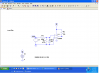
My circuit looks like this:
Clipboard01.jpg

In PSpice everything looks fine:
Clipboard02.jpg

But real circuit doesn't work properly. It looks similar to this:
Clipboard03.jpg

I don't know in which exact moment of time there is high voltage (3.3 V), cause I have only one-channel oscilloscope.
I suppose this problem can be related with GND.

I will be grateful for any help.

Greetings,
Michal
 
Last edited:
hi mical,
Are you trying to get an equal on/off time of the pulse at the output.?

If Yes, you will have to add a small offset voltage that sets the non inverting to 0v.

Another problem with LM393 is that if an input voltage goes higher than the Vsupply -1.5V, the outputs can invert.

EDIT:
Add this divider resistor
Reduce the AC input at the LM393 pin to less than 2Vac
 

Attachments

  • Clipboard01.jpg
    Clipboard01.jpg
    26.2 KB · Views: 368
Last edited:
Hello all,
sorry for refreshing this old topic, but I haven't solved this issue yet (I had a little break).
I've modified my circuit, but it still doesn't work properly.

To display signals I use digital scope (sound card + visual analyser).

My circuit (A, B, C are measuring points):
clip00.jpg

Transformer output voltage (point A):
clip01.jpg

Negative input voltage (point B):
clip02.jpg

Transformer output voltage (point A) and output voltage (point B):
clip03.jpg

Negative input voltage (point B) and output voltage (point B):
clip04.jpg

My question:
1. Why negative input voltage (point B) is not a sine wave? It looks like voltage measured on diode.
2. Could be this voltage a reason of inappropriate output voltage (intentionally it should be square wave - described in my previous post) ?
3. If not - what should I modify?

Thanks in advance for your reply,
regards
Michal
 
They also don't like much current below ground. Try making the input resistor larger and add a diode to prevent the voltage from going much below ground.
 

Attachments

  • comp.PNG
    comp.PNG
    57.8 KB · Views: 337
Hello,
I have to connect output of the comparator with microcontrollers input.
What would be the best way to reduce output voltege:
- use a voltage regulator eg. LF33
- use a voltage divider
- use something else
?

Thanks in advance for your reply,
regards
Michal
 
Hello,
I have to connect output of the comparator with microcontrollers input.
What would be the best way to reduce output voltege:
- use a voltage regulator eg. LF33
- use a voltage divider
- use something else
?

Thanks in advance for your reply,
regards
Michal

hi,
A voltage divider is the simplest option.
 
If the pull up resistor on the output of the 393 is tied to 3.3 volts, why do you need a lower voltage?
 
If the pull up resistor on the output of the 393 is tied to 3.3 volts, why do you need a lower voltage?

hi Ron,
Your diagram in post #4, shows it connected to +9V, perhaps the OP doesn't realise that the resistor to +3.3V is an option.?

E
 
If the pull up resistor on the output of the 393 is tied to 3.3 volts, why do you need a lower voltage?

Right, I will try to reduce supply voltage to 3.3 V.

PS. Sometimes it's very hard to find the easiest way ;)
 
Last edited:
Right, I will try to reduce supply voltage to 3.3 V.

PS. Sometimes it's very hard to find the easiest way ;)

hi,
Keep the 9V supply to the LM393 IC if you prefer, but connect the top of the resistor to 3.3V. In that way the output will switch between 0v and 3.3v
 
Last edited:
Status
Not open for further replies.

Latest threads

New Articles From Microcontroller Tips

Back
Top