Continue to Site

Welcome to our site!

Electro Tech is an online community (with over 170,000 members) who enjoy talking about and building electronic circuits, projects and gadgets. To participate you need to register. Registration is free. Click here to register now.

  • Welcome to our site! Electro Tech is an online community (with over 170,000 members) who enjoy talking about and building electronic circuits, projects and gadgets. To participate you need to register. Registration is free. Click here to register now.

Clock Timer : School Project

Status
Not open for further replies.
I'm not understanding properly in you first paragraphs, but I have school tomorrow and i'll just ask about what you are saying (which might help with my understanding)...

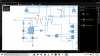
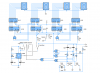
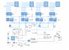
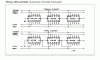
Apparently the current between the 7 segment displays are 13mA and a voltage of 2.4V. Which I thought was the standard rating for them but might be wrong. Correct If i was wrong, Thanks so much :)
 
hi C.
On CMOS devices it is important that you do not have Inputs 'floating' ie: not connected either High or Low, I did point this out many posts ago.

Ref the switch to the 555, its bad practice to switch Off the power to a device when it is connected to other parts of the circuit which are active.

Your simulator may show your circuit working OK, but when you build it will not work as expected.

E
 
Oh I get it, so like this then ???
upload_2015-8-23_17-30-51.png
 
Consider this option, use the 555 RESET pin #4

As I said before the use of a diode on the output is bad idea, rethink it.
 

Attachments

  • upload_2015-8-23_17-30-51.png
    upload_2015-8-23_17-30-51.png
    71.4 KB · Views: 223
Look at this option.
 

Attachments

  • timer1.png
    timer1.png
    26.4 KB · Views: 219
Brilliant, works good as new. Could I ask, what are the resistors for?

As I have said a number times, 'floating inputs' to the IC's

A CMOS IC input pin has very high input impedance [resistance], so if left unconnected it can pick up a static charge, this charge could be high enough to register with the IC as a genuine input High.
Just moving your hand near the circuit board can effect this static charge and the circuit will malfunction.
To prevent this problem the input pin is connected to +V or 0V via a pull up or pull down resistor, depending upon the IC's function,, the resistor holds the pin at +V or 0V whenever the pin is unconnected to another part of the circuit.

OK?

Corrected a typo.!
 
What they mean by using a bus is this. It is a way to show a bunch of wires with just one thick wire so it makes circuits easier to read. Imagine showing all the wires on a 64 bit data bus, zowie what a mess. As an example I made a quick diagram to illustrate. Any schematic software worth its salt should be able to draw buses. Any questions?
 
hi C,
Look at this option for enable/reset and clocking.

E
 

Attachments

  • timer2.png
    timer2.png
    34.4 KB · Views: 214
Thanks MikeBits for the new knowledge but for the perpose of making a simulating schematic I can't really do that :) Thanks so much anyways

Oh yeah, I'll look into that thanks eric
 
One other point where are the current limiting resistors for the LED Displays.?

Also have you looked at the/TC pin 7 for carry/borrow.?
 
LEDs: 2.4 V at (10-20 mA) is a good start if you don't know the real characteristics. Generally, this is for a standard RED LED.
Different colors change the forward voltage. There are also high efficiency LEDs. Some LEDs have built-in current limiting resistors. e.g. 12 V and 5V LEDs.
Peak currents that the LED can withstand are a lot higher.

The resistor choice gets more critical as the supply voltage is lowered and you MAY have to take into account the range of Vf, but usually Vf max is OK.
 
CMOS was designed for low power operation and the logic levels are essentially the power rails. Floating inputs can settle anywhere increasing the power disipation. What usually happens is unintended oscillation that results in high chip temperature and failure.

For now, the rule is connect unused inputs to Vcc or Ground. The real rule is to connect to the logic level that results in the lowest power dissipation and through a resistor if you can.
 
LED resistors:

See the datasheet page 6. https://www.futurlec.com/4000Series/CD4511.shtml

The equivalent circuit shows Vdd. an unvalued resistor, a transistor and an LED segment.

Find the value of the resistor?

So, you have the display specs. I'll use 20 mA and 2.4 V which means the LED drops 2.4V maximum or so.

So if, Vcc = 5V
LED: Max Vf=24; 20 mA nominal
Diode drop: People use anywhere between 0.6 and 0.7 V. Knowing the transistor type, we could use the max value of Vce(Sat). The diode drop is temperature dependent and therefore a diode is a good temperature sensor. The slope is material property.

So, R <= (Vdd-V(CEsat)-Vf(LED))/20 mA

Note, I used 20 mA, which means 20E-3 Amps.

You can always use kohms and mA or ohms and Amps to get R. e.g. (10*1e3)/(20*1e-3)
Adding exponents, you get 10/20 E0 o 10/20 where the 10 is 10K and the 20 is in mA also has units of Ohms.

Early on you should note that the units are capitalized if it's derived from a proper name. Amps, Volts, Watts, Siemens(1/Ohms), Hertz. Watch out for m for milli (1e-3) and M for Meg (1e6). So, there is a BIG difference between 10 mHz and 10 Mhz.

The Siemen unit used to be known as a mho or ohm spelled backwards,
 
Last edited:
Please explain, haven't learnt about that?

When you cascade 4510's to form an Up/Dn counter you can use the existing pins on the 4510's rather than AND gates.
Look at this image, I prefer the synchronous/parallel method of clocking.

Google: Cascading 4510 for more info.

E

BTW:
I assume the mode of operation is that you manually increment the counter to say 30 secs and then use the 555 output to decrement down to zero.???
How do you plan to stop the down count when it reaches 00.??

IF the maximum count is some fixed value between 1 and 99 you could use the Parallel Load to preset the counter to this value.
 

Attachments

  • AAesp01.gif
    AAesp01.gif
    53.1 KB · Views: 220
Last edited:
Status
Not open for further replies.

New Articles From Microcontroller Tips

Back
Top