Continue to Site

Welcome to our site!

Electro Tech is an online community (with over 170,000 members) who enjoy talking about and building electronic circuits, projects and gadgets. To participate you need to register. Registration is free. Click here to register now.

  • Welcome to our site! Electro Tech is an online community (with over 170,000 members) who enjoy talking about and building electronic circuits, projects and gadgets. To participate you need to register. Registration is free. Click here to register now.

Clock Timer : School Project

Status
Not open for further replies.

Canyouknott

Member
Hi, I'm a student in year 11 at the moment and are studying Electrons...

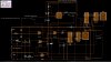
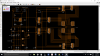
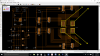
I have started to construct a circuit diagram of a chess clock. That are two main functions on my design which are 'Selecting the time' and 'Starting the timer'...
It's pretty start forward by looking at the labbled switches in the diagram but if there are any questions about it, please do ask...
But the reason I am here on this forum is to ask if it is possible to add more digits to each opponents clocks???

Thanks in advanced **Keep in mind that I have just started Electronics and not a professional yet Cheers :) **
 

Attachments

  • Circuit.jpg
    Circuit.jpg
    191.2 KB · Views: 366
Wait, isn't it possible to add a nand gate which will connect to output 1 and output 8 of 4511IC, then the output of the nand gate is connect to a input on another 4511IC connect to another 7 segment display
 
Yes it should be easy to add more digits to the clocks, but I will leave that for others to discuss with you.

What I will comment on is the drawing of the schematic.
As is often the case with beginners, there are wires crossing all over the place and badly routed.
This makes it difficult to see what is happening in the circuit.
Example, you have three push buttons with pull-up and debounce, electrically they are identical*, but they are all drawn differently.
(* well almost, one has a voltage limiter with a couple of diodes, I am sure that you don't need that in this application).

I have redrawn the schematic to try and show how it can be simplified to make it easier to read and understand.

Canyouknot edited.jpg


Welcome to the forum.

JimB
 
The schmatic you just saw before was just like a draft to see if this circuit works but then I improved a bit (i think) by making it neater and adding a extra didgit
 
Just to clarifly the buttons and switchs...
Reset (bottom Left) - Resets both timers to 00-00
Input Allower (Above Reset) - Allowers pulses into the circuit
Pulse (About Input Allower) - Pulses the timer which changes the amount of seconds you want to play with
Switch above Pulse should be active when selecting the time but off when not selecting
Switch above that swaps between players so you can select a differnet amount of time on each side.
Timer ON - Starts the 555 timer pulses onto the 7 segment displays
Swap Players - Once a player finishs there turn they switch the switch which starts the oppenents timer and stops there, so on and so forth.
Up/Down. - When selecting or playing you are able to change the direction on the number e.g. 1,2,3,4 (Switch) 3,2,1,0

Thanks :)
 
I made a quick improvement which is replacing the switches with dpdt switches.... The first dpdt swich swaps players will selecting the timer and playing.. The other dpdt swaps the circuit mode from selecting a time to starting the timing period..
upload_2015-8-22_15-23-51.png
 

Attachments

  • upload_2015-8-22_15-24-57.png
    upload_2015-8-22_15-24-57.png
    90.6 KB · Views: 252
The same problem appears as before - too many cross lines, not quite readable. Move the 7-seg. displays as shown and correct lines.

You can actually do two things to simplify: to use bus line or hide it completely (wire name pointers remains only).
 

Attachments

  • Sample.png
    Sample.png
    86.1 KB · Views: 272
hi Can,
It is much better if you arrange the LED's along the top of your circuit, below them the LED drivers, below them the counters.
Place the LSD on the Rightside of your diagram.

Do you follow OK.
E

EDIT:
As per this example.
 

Attachments

  • 3DecadeUpDownCntr1.gif
    3DecadeUpDownCntr1.gif
    42.2 KB · Views: 359
hi,
To avoid having all the power lines and the Ground lines routed thru your drawing, its usual to use a small downward pointing triangle for 0v.

Likewise the Power rails could be a small circle or square,,, providing you also label the actual power supply with these symbols, others can follow your diagram.

EDIT:
As per this image.
 

Attachments

  • AAesp01.gif
    AAesp01.gif
    7.6 KB · Views: 270
Are you meaning like this kinda?

Well, yes. However this is just a simple tweak. Make it more compact and keep the logical parts together.

The golden rule is to keep the schematic as clear as it can be. It purpose is to clearly show the logic of the circuit or its parts (keep it in group). These who looking at it shouldn't get lost in bunch of unnecessary wire mess... :)

As suggested, use the bus lines or hide it completely in such cases with many wires.
 
Status
Not open for further replies.

Latest threads

New Articles From Microcontroller Tips

Back
Top