Hi,
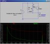
I'd be very grateful if somebody much cleverer than me could explain how the attached circuit works. 28VDC at G and the output at D is a solenoid coil.
It is described as; when 28VDC is applied at G, 28V is initially present at D (to drive the solenoid) and then tails off to 6V (to hold the solenoid and prevent excessive heat build up).
I'm guessing the schematic may have been over simplified or I'm just too simple to get it ;-)
Many thanks in advance.