Continue to Site

Welcome to our site!

Electro Tech is an online community (with over 170,000 members) who enjoy talking about and building electronic circuits, projects and gadgets. To participate you need to register. Registration is free. Click here to register now.

  • Welcome to our site! Electro Tech is an online community (with over 170,000 members) who enjoy talking about and building electronic circuits, projects and gadgets. To participate you need to register. Registration is free. Click here to register now.

canon 540ez flash, Capacitor ?'s

Status
Not open for further replies.

CalebG

New Member
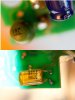
Hello, I am attempting to repair my canon flash, In testing I have located some capacitors that appear to be bad. the first is the green tantalum that is testing at several ohms esr, however I am not sure what the printing is supposed to say? What value should I replace it with? Then again I havent done any previous testing of tantalums for esr, do they normally run high?

the second is the silver mica cap that is testing open, in looking through my junk box for a replacement I found a vcr board with a dozen on it, my question though is that all the similar values are also showing high esr. are they all bad as well or do the silver micas also have high esr's normally?

I was hoping to be able to repair with parts from my junk box and save a trip into town, so thanks for clarifying. Caleb
 

Attachments

  • caps.jpg
    caps.jpg
    132.9 KB · Views: 605
Well, umm...the green thing isn't a capacitor, it's a 1ohm radial choke...and the silver mica capacitor is in fact a polypropylene/ foil 0.0022uF capacitor unles my glasses need cleaned...

rgds
 
Thankyou for taking the time to enlighten me, so if the choke is testing more than 1 ohm is it bad or not? as for the cap do I need to use a identical polypropylene/ foil replacement, or can I go for a regular poly cap? I could not decipher a voltage rating from the HH2E code.
 
Last edited:
For the choke I would expect a resistance reading of anything up to around 8-10 ohms, over that I might be suspicious. The capacitor won't be rated much higher than about 100V due to the size of the pinout, 63V is more likely. Unless it is obviously blown, I suspect your problems lie elsewhere. Check around the discharge capacitor, it will be rated above 200V at 10-20uF, make sure it is charging. Other common problems are transformer windings going open circuit, but quite often it is a broken wire right at the leg due to being bumped around etc. Above all else, be careful where you put your fingers, these flash guns can give you a nasty one...

rgds
 
Thankyou, all the electrolytics are testing good, the choke was about 7 ohms as I recall, and the cap is testing completely open. I am not getting any power to the secondary board so I think the trouble is on the primary power board, although there were 2 broken wires on the ttl sensors when I opened it as well as corroded contacts in the battery compartment. I will check the transformer windings when I get home tonight. thanks again.
 
Ok then, both transformers test ok as well. I still haven't found a good replacement for the cap. out of the 6 222's I found in my junk bin every single one is testing open. So I guess I will have to go up to the supply house sometime soon and get a new one.
 
You say testing open circuit, exactly how are you measuring the capacitance?
These caps are itsy bitsy tiny, you won't get much from them, particularly if your fingers are holding the test probes on the leads etc.
If you can take some really clear close up pics of both sides of the boards and post them here, maybe we can get a clearer idea of where the trouble lies...

rgds
 
I was beginning to wonder if the cap was actually good, I am using an esr meter I built from the Homo-Ludens schematics. when I test with my capacitance meter it is giving the correct value. I found another 3 222 caps today in my junk box and all are testing open with the esr meter. I find the idea of them all 9 being bad pretty far fetched. although the meter tests 223's just fine, I think they may just be too small. I partially reassembled the flash so I could do some further testing and I now have voltage up to the first transformer, I have to mcgyver up a temporary power supply to be able to test it disassembled. I will however get some good pictures up for you to peruse tomorrow. Thank you again for your help. Caleb
 
Ok here are the pics of the two main boards, I further dissembled the lcd board and the opposite side has a lot of corrosion that may be adding to the problems
**broken link removed**

Yes I know, but you did ask for high res
 
Ok, what you need to do is check that the charge pump is working properly. Let's measure the high voltage on the discharge capacitor. It will be the electrolytic one with the highest voltage and the largest size. Set the Flash gun up ready to fire and measure the voltage across the capacitor. You should see something in the order of 200-250V on it. If that's ok, then the next thing to do is identify the trigger circuit and manually trip it to see if the flash tube does actually fire.

You will have to rig up a power supply for this, easiest way is with one of those wee battery pack frames you can buy, saves a whole lot of hassle. Alternatively, if you have a variable bench supply, you could just wire up to the onboard battery contacts, either way is fine, but make sure you limit the current if you are using a bench supply. Never work on it without the tube being properly connected, if it's going to fire accidentally, you want the tube to take the hit and not your fingers!

rgds
 
Thanks, but the flash wont even come on yet. there were several corroded contacts on the lcd board that were shorting to adjacent pins and the two left push buttons were shorted together. I carefully scraped as much corrosion as I could off clearing the shorts and other faults, I was wondering if the corrosion on the though holes causes them to go open easily? will they need resoldered? the switch to turn the flash on is the two large contacts on the last picture, as I followed out the leads they lead directly to the ic on the other side of the board. So I am now wondering if the corrosion was causing the problems? And since it looks like maybe someone dropped it into salt water what are the chances the ic's survived intact? I will dig out a battery carrier and reassemble to see if functionality has improved and run the tests you requested.
 
I suppose it is possible if the corrosion was left unchecked that it could eat away the tracks, but I don't see any obvious evidence of this from the photos.
If the solder joints look like they are dry/ broken, a freshen up with an iron won't hurt, but only resolder the obvious bad ones. Old solder sometimes looks like it's a problem, but it's really only dull(no longer nice and shiney). The IC's themselves won't be affected by the salt water, the board itself should be well cleaned and dried. More of a concern would be the flash being charged at the time it was dropped into the water, causing discharge paths that might damage the ic's or other discreet semiconductors.
 
well I tried again with a power supply hooked up and I am getting voltage to the on off switch but still no love from the flash. I think this one is beyond me for the moment, reassembled and stuck on the shelf for now. I will see if I can get another unit for parts and try switching out the lcd board.
 
Thanks for the help, I was able to repair a nice 19" lcd I got for free on friday, took less time to open, isolate, and repair than it did to get the spot some bonehead wrote bad on the screen in paint pen off. gotta love crappy filter capacitors : )
 
Capacitor faults account for probably 70% of my workload, so it's no surprise. I don't take anything less than 22" monitors as presents now ;)

I have a couple of HP ones that were going to the scrap that simply needed capacitors replaced in their power supplies. I also have a nice Samsung 18" widescreen that I was given for "spares" that only needed the smt fuse replaced on the inverter board. Cosmetically bringing a monitor back to life is, however, sometimes more work than the repair itself, so it's always a balance. Those I'll generally strip and recycle the screens etc.

I hate seeing saveable gear going to the landfill, but these days it's like it's almost mandatory...

rgds
 
I have two units of the same flash Canon Speedlite 540EZ. The first one gives the squeal for a few seconds as it charges, an then the sound dies out and it doesn't charge at all. This after a few previous times in the recent weeks when the charging time was longer than usual. The other doesn't even do that - it's totally mute and doesn't charge. I opened the 2nd one, and didn't find any physical issues I was expecting, but I suspect it to be the big capacitor at fault for both of them. I have yet to have a bare view of the big cap on the unit I opened, but it doesn't show any physical symptoms as I expected since the housing it is in is intact and all looks clean.

The cap is **broken link removed**.


Capacitor faults account for probably 70% of my workload, so it's no surprise.

What proportion of those do show any clear physical symptoms like bulges and leaks, and what proportion look all okay but test fail?

Update:

Tested the caps on the 2nd unit using a Digital Multi Meter using the resistance testing. Test is supposed to answer preliminary questions about the caps - on connecting the test leads if the resistance steadily increases the cap is getting charged from the DMM's battery, and if the increase abruptly halts the electrolyte is not okay, and if it shows continuity or the lack of it, it is understood to be shorted or open respectively.

What I have found is that the 222J(circled in blue) stays constant at 269kΩ (I believe it to be okay?) and the cap circled in orange(the blue cap nearer to the center of the board) stays at a constant of 1.75kΩ which I believe to be not okay. I'll have to desolder it and test it further. The rest of the caps were within expectable behaviour, so I didn't test them further.

View attachment 66031

Update2:

Unit 1 seems to be all okay - testing using a nokia phone charger's 5.7v supply(which reads 5.95v on the DMM) the flash shows to be as per expected functionality. The individual AA cells read near to 1.3-1.35v on the DMM, so I didn't expect them to be a big reason for the flash unit to not charge up.

Unit 2 charges(without anything done on it yet at all :D), and the big cap shows 165v DC across its terminals, but doesn't get to the 'full charge' red light indicator - it only stays green to indicate a partial charge ready for one shot. Its xenon tube seems cracked due to use. There is also indication of some burn around one of its ends, and signs of some 'exhaust' spewed around.

The cap above circled in orange has a 2.2kΩ SMD resistor in parallel.
 
Last edited:
The proportion of ones that look fine to the ones that don't is around 90% looking fine and dandy with 10% obviously looking duff, and a few of those actually work fine, but in non critical circuits. The only way to be sure that the capacitor is operating correctly, would be to test it correctly. Using an ohm meter will tell you very little about the average performance of the capacitor, for that you need an ESR meter. In the case of your camera flash, this has a small switching supply of sorts charging the capacitor, if the capacitor has a high internal resistance there is every chance that the smps will simply foldback and shut down. Unless you have access to an ESR meter, testing it by substitution is the only other sensible option :) Of course, your problem may also lie elsewhere in the circuitry.
 
Last edited:
Update3:

The xenon tube has been replaced with a brand new one.

The flash unit still doesn't charge beyond the green quick flash indicator, and on a 6v duracell battery the big cap shows 250v DC across its terminals. It still doesn't fire the flash when the test button is pressed.

Inside the flash head there are two resistors in series of which one is burnt, as indicated in the pic below.

View attachment 66249

It measures 'out of range' on my DMM when on board, but reads 19.6kΩ when desoldered and measured. Could anyone who has an opened 540EZ let me know the resistor's colour code & value? Best also would be to include a picture of the board itself. :)

Update: Found it out from the other flash unit - the burnt resistor is supposed to be 22kΩ with 5% error. It is (Red, Red, Orange, Gold). By the next update, I guess I will encounter another issue to solve. :)
 
Last edited:
Some funny/suspicious behaviour on this part of the PCB: There's a 20E6 diode that shows forward voltage correctly only when removed from the circuit, and continuity when in circuit(it is in parallel with the big coil of wire... ). Then, the newly replaced 22kΩ resistor shows 21.1kΩ very very slowly like in 10 minutes or so it reaches 21.1kΩ on the DMM, while it reads near to 22kΩ as usual when out of the circuit. :confused:

I wonder what might be causing the resistor to behave like that.

Update: Seems like the answer is this - it looked like the cap-charging behaviour of the preliminary test for cap using an Ohmmeter, and sure it seems like that's what is happening! There are two wires from the positive terminal of the big cap, one of whom goes to the charging board and the other to the trigger board pictured in the above post. Keeping both red wires in circuit displayed the behaviour as above, while removing either one of them got the Ohmmeter reading the resistor immediately.
 
Last edited:
Status
Not open for further replies.

New Articles From Microcontroller Tips

Back
Top