Electro Tech is an online community (with over 170,000 members) who enjoy talking about and building electronic circuits, projects and gadgets. To participate you need to register. Registration is free. Click here to register now.
Welcome to our site! Electro Tech is an online community (with over 170,000 members) who enjoy talking about and building electronic circuits, projects and gadgets. To participate you need to register. Registration is free. Click here to register now.
I wouldn't recommend it. Looking at the datasheets, the SL100 has some voltage ratings that are a good 20v or more higher than the maximum specs for the BD135. While it might work, it's a little risky, especially in an inverter circuit.
If you are ever looking for an equivalent transistor, look at the datasheets. Make sure the one you're replacing with has an equal or higher voltage rating and current rating. Also (obviously) make sure they're of the same type, and designed for the same application (switching, amplifying, etc). You can get all the info you need from the datasheets.
SL 100 is used as a 1st amplify stage. I thought it is not more critical replacing with BD135. Due to my cell phone's network problem it has been double thread of same question. One thread has picture attached, but you got a thread without a picture, Please look at this picture and suggest me..
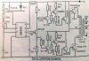
It is a very poor quality very old inverter circuit.
It has a square-wave output that is rectangular instead of square. It can drive a heater or incandescent light bulbs. It cannot power most electronic products or an electric motor that has an electronic speed control.
Its voltage will be too high with a low load and will be too low with a heavy load because it has no voltage regulation.
If the output power is 200W then the current from the battery, in the output transistors and transformer must be 200W/12V= 16.7A. Then each output transistor has 4.2A.
The driver transistor current is a max of 0.84A and the current in the pre-driver transistors is only 16mA. Then the current in the SL100 transistors is almost nothing so any little transistor can be used.
Most simple square-wave inverters use a CD4047 oscillator that has a digital divider and has two opposed outputs giving a PERFECT square-wave. Then the antique BEL547 transistor and maybe the SL100 transistors are not needed.
Here is a 100W square-wave inverter. Add some paralleled output transistors (and power the ICs from a zener diode):
100W from a 12V battery is a current in each output transistor of 100/12= 8.3A.
The minimum hFE of the 2N3055 output transistors at 8.3A is 6 so the maximum current in the driver transistor is (8.3/6=) 1.38A.
The maximum allowed current in the 2SC1061 transistor is 3A. The maximum allowed current in a BD135 is only 1.5A but it might work until there is a current spike.
The 2SC1061 has 4 levels of hFE at 1A from 35-70 for an A version to 160-320 for a D version. The maximum current from the opamp is only 20mA so an hFE of (1.38A/20mA=) 69 is needed but the minimum hFE for a BD135 at 1.38A is almost nothing.
A TIP41 transistor also does not have enough minimum hFE.
And what about D1 and D2, what is "2A"? Equivalents of 1N4007 or 1N4148?
I'm trying to understand what D1 and D2 are doing. Obviously each one conducts when it's side of the transformer is switched off - but I can't make a mental leap from there that doesn't involved destroyed transistors.... Please help!
I think the diodes do nothing.
They were in the original circuit nthat worked very poorly.
The transistor conducts and its collector goes to near ground. When the other transistor conducts and the first transistor turns off then its collector goes to positive 23V (not a negative voltage) due to center-tapped transformer action.
The collectors never try to go negative.
A squarewave inverter is not modern. It is old, simple and crude. The one I posted has poor voltage regulation and does not shut down when the battery charge becomes low so it kills batteries.
A cheap "modified sinewave" inverter is fairly modern.
A more expensive and fairly complicated pure sinewave inverter is modern.
I think your inverter circuit with the SL100 transistors has too many transistors. The CD4047 IC can replace its 555 oscillator and phase inverter transistor.
Yes.
But the circuit is silly:
1) With an output of only 200W then each output transistor has a current of only 4.2A but they are rated for 15A.
2) The driver transistor is also rated for 15A but does not need more current than 1.7A and nothing limits its current so it will get extremely hot.
3) The pre-driver transistor is another transistor rated for 15A but does not need more current than 170mA.
4) The SL100 transistors do not need more current than only 17mA.
The output , driver and pre-driver transistors need base to ground resistors to quickly turn them off.
This site uses cookies to help personalise content, tailor your experience and to keep you logged in if you register.
By continuing to use this site, you are consenting to our use of cookies.

")