RoveyDoveyGrovey
New Member
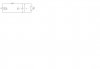
Basically i've been asked to prove that by changing the capacitor value in the circuit (see attached) this equation is true (Simulated in PSpice)
Vripple = (i/c) * t
or
Vripple = i/(cf)
where,
i = current
c = capacitance
t = time (1/freq)
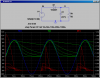
As this is a half wave rectifier with an input voltage of 10vpkpk at 50Hz, with c= 10uF the output goes up to about 9v and then down to 0v in the simulation, so the ripple is about 9v.
I measured the current as about 187mA at its peak, c = 10uF and t = 1/50Hz
stick that in the equation and Vripple = 374v I think not!!
The only thing I can think of is that im measuring the current in the wrong place, but i've tried everywhere and I still get a stupid answer.
Obviously if you rearrange the equation,
Vripple*cf = i
9v*10uF*50Hz = 4.5mA
I cant find 4.5mA anywhere in the circuit.
Please help, thanks
Vripple = (i/c) * t
or
Vripple = i/(cf)
where,
i = current
c = capacitance
t = time (1/freq)
As this is a half wave rectifier with an input voltage of 10vpkpk at 50Hz, with c= 10uF the output goes up to about 9v and then down to 0v in the simulation, so the ripple is about 9v.
I measured the current as about 187mA at its peak, c = 10uF and t = 1/50Hz
stick that in the equation and Vripple = 374v I think not!!
The only thing I can think of is that im measuring the current in the wrong place, but i've tried everywhere and I still get a stupid answer.
Obviously if you rearrange the equation,
Vripple*cf = i
9v*10uF*50Hz = 4.5mA
I cant find 4.5mA anywhere in the circuit.
Please help, thanks