Electro Tech is an online community (with over 170,000 members) who enjoy talking about and building electronic circuits, projects and gadgets. To participate you need to register. Registration is free. Click here to register now.
Welcome to our site! Electro Tech is an online community (with over 170,000 members) who enjoy talking about and building electronic circuits, projects and gadgets. To participate you need to register. Registration is free. Click here to register now.
Here the whole thing I looked at the zip it should have all the file that was used It don't look right the zip is what mplab makes I'll zip the whole folder and post it after you look at what mplab ziped
3v0 my C18 doesn't have that linker so I looked in this computer and it c18 has it going to build here and see what happens see take a look it doesn't
have that in MPLAB-C18-Academic-v3_31
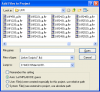
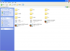
3v0 take a good look at the pic there is no C:\MCC18\LNK the linkers are in bin this is
MPLAB-C18-Academic-v3_31 and i install it two time and it still installed the same
Please download the zip file from the webpage which contains a fully working project.
Microchip has replaced all the C18 linker files with new ones ending in _g.
The release notes have info on backwards compatibility. I have to rework the interrupt code. In the short run using the old 18F1320.lkr or 18F1320i.lkr file will result in a correct executable.
I need to thank Burt for sticking to his guns on this one. The code has worked without problems for over a year. I was initially quite sure it was operator error. The problem was that Microchip made a change to the linker file which exposed what was up to then a harmless bug in my code.
Look dad no linker That worked LOL it runs like it should Thanks MiKe and 3v0 now I no
i wasn't setting it up wrong. The new C18 sets all the setting mostly for you and the linker
Its to control an lcd. I happen to have an LCD with a HD44780 driver, and am using C18, so it seemed good. I am getting errors while trying to compile, first there were problems with 4 of the config commands, it didnt recognize them, and I cant find what they are supposed to be, just to test I commented them out, then it generated an error at line 43, the very end of the main function right where the closing bracket is, so not a real helpful direction, just said "syntax error". Heres the code as I have it pasted:
main.h
Code:
#include <p18cxxx.h>
#include <stdio.h>
#include <delays.h>
#include "LCD.h"

//#pragma config OSC = INTIO67  //Internal oscillator
//#pragma config FCMEN = OFF //these are the 4 I commented out
#pragma config IESO = OFF
#pragma config PWRT = ON
//#pragma config BOREN = OFF
#pragma config WDT = OFF
#pragma config MCLRE = OFF     //MCLR is disabled
//#pragma config PBADEN = OFF
#pragma config LVP = OFF

void delay1s() {
	Delay10KTCYx(200);
}

//User defined putc for user defined output stream
void _user_putc(unsigned char c) {
	send_data(c); //Send character to LCD
}

void main() {
	OSCCON = 0b01110010; //8 MHz
	TRISC = 0x00; //PORTC is all output
	stdout = _H_USER; //Set to user-defined output stream via _user_putc

	lcd_init(); //Initialize the LCD
	send_cmd(0x0C); //Turn off cursor

	set_cursor(1, 1); //Set cursor to row 1, column 1
	printf("Hello!"); //Print "Hello!" to the LCD

	set_cursor(2, 1); //Set cursor to row 2, column 1
	printf("HD44780");

	while(1) {
		delay250ms(); //Scroll the display 1 character right every 250 ms
		sc_r();
	}
}
lcd.h
Code:
/*
 * PIC 16F886 HD44780 LCD Driver
 * Author:    solarwind
 * Date:      2009-01-31
 * Email:     x.solarwind.x@gmail.com
 * Compiler:  Microchip C18 (v3.22)
 *
 * Pin Configuration:
 * 		The LCD's data 4 - 7 pins should be connected to bits 4 - 7,
 * 		respectively, of any port you wish to use on your PIC.
 *
 * 		The E, R/W and RS pins can be connected to any unused port at
 * 		any pin.
 *
 * 		My configuration is as follows:
 * 		LCD        PIC
 * 		16 BK-
 * 		15 BK+
 * 		14 D7   -> RC7
 * 		13 D6   -> RC6
 * 		12 D5   -> RC5
 * 		11 D4   -> RC4
 * 		10 D3
 * 		9  D2
 * 		8  D1
 * 		7  D0
 * 		6  E    -> RC0
 * 		5  R/W  -> RC1
 * 		4  RS   -> RC2
 * 		3  VO
 * 		2  VDD
 * 		1  VSS
 *
 * Note:
 * 		This driver is designed to work with almost any PIC 18. Be sure to
 * 		correctly initialize your PIC, correctly connect your LCD and
 * 		define your connections below.
 *
 * Note:
 * 		DDRAM Addresses are as follows on 16 x 4 displays:
 *
 * 		Line 1:  0x00 -> 0x0F
 * 		Line 2:  0x40 -> 0x4F
 * 		Line 3:  0x10 -> 0x1F
 * 		Line 4:  0x50 -> 0x5F
 *
 */

#ifndef LCD_H_
#define LCD_H_

#include "main.h"

//Define your LCD's data PORT here:
#define LCD_PORT PORTC

//Define your LCD's control pins here:
#define LCD_E  PORTCbits.RC0 //Enable
#define LCD_RW PORTCbits.RC1 //Read/write
#define LCD_RS PORTCbits.RC2 //Register select

void strobe(void);                      //Strobes the enable pin of the LCD
void send_nibble(byte b);               //Send high nibble of byte b to LCD
void send_byte(byte b);                 //Send entire byte b to LCD via 4 bit interface
void send_cmd(byte b);                  //Send command to LCD
void send_data(byte b);                 //Send data to LCD
void set_cursor(byte row, byte col);    //Set cursor position at (row, col)
void cursor_on(void);                   //Turn on cursor
void cursor_off(void);                  //Turn off cursor
void cls(void);                         //Clear screen
void sc_r(void);                        //Scroll all lines one character right
void sc_l(void);                        //Scroll all lines one character left
void home(void);                        //Send cursor to top-left position
byte b2hc(byte data);                   //Convert lower nibble of byte data to an ascii character
void lcd_init(void);                    //Initialize LCD

#endif /*LCD_H_*/
lcd.c
Code:
#include "LCD.h"
#include "delay.h"

void strobe() {
	LCD_E = 1;
	Nop();
	LCD_E = 0;
	Nop();
}

void send_nibble(byte b) {
	LCD_PORT = (LCD_PORT & 0x0F) | (b & 0xF0);
	strobe();
}

void send_byte(byte b) {
	send_nibble(b); //Send high nibble
	send_nibble(b << 4); //Send low nibble
}

void send_cmd(byte b) {
	LCD_RS = 0; //Command mode
	send_byte(b);
	delay5ms();
}

void send_data(byte b) {
	LCD_RS = 1; //Data mode
	send_byte(b);
	delay100us();
}

void set_cursor(byte row, byte col) {
	byte command = 0x80;
	switch(row) {
	case 1:
		command += col - 1;
		break;
	case 2:
		command += 0x40 + col - 1;
		break;
	case 3:
		command += 0x10 + col - 1;
		break;
	case 4:
		command += 0x50 + col - 1;
		break;
	default:
		command += col - 1;
		break;
	}
	send_cmd(command);
}

void cursor_on() {
	send_cmd(0x0E);
}

void cursor_off() {
	send_cmd(0x0C);
}

void cls() {
	send_cmd(0x01);
}

void sc_r() {
	send_cmd(0x1E);
}

void sc_l() {
	send_cmd(0x18);
}

void home() {
	send_cmd(0x02);
}

byte b2hc(byte data) {
	switch(data & 0x0F) {
	case 0:
		return '0';
	case 1:
		return '1';
	case 2:
		return '2';
	case 3:
		return '3';
	case 4:
		return '4';
	case 5:
		return '5';
	case 6:
		return '6';
	case 7:
		return '7';
	case 8:
		return '8';
	case 9:
		return '9';
	case 10:
		return 'A';
	case 11:
		return 'B';
	case 12:
		return 'C';
	case 13:
		return 'D';
	case 14:
		return 'E';
	case 15:
		return 'F';
	}
	return 0;
}


void lcd_init() {
	delay100us(); //Delay for LCD to start itself up

	LCD_E = 0;
	LCD_RW = 0;
	LCD_RS = 0;

	//Start initializing the LCD
	send_nibble(0x30);
	delay5ms();
	send_nibble(0x30);
	delay5ms();
	send_nibble(0x30);
	delay100us();
	send_nibble(0x20); //4 bit interface
	delay100us();

	send_cmd(0b00101000); //Function set: 4 bit interface
	send_cmd(0b00001110); //Display on/off: display on, cursor on, blink off
	send_cmd(0b00000110); //Entry mode: increment, no shift
	send_cmd(0b00000010); //Cursor home
	send_cmd(0b00000001); //Clear DDRAM/LCD
	delay5ms();
}
delay.h
Code:
#ifndef DELAY_H_
#define DELAY_H_

#include <delays.h>

//Required for LCD
void delay5ms(void);
void delay100us(void);

//Useful for user
void delay1s(void);
void delay250ms(void);
void delay100ms(void);

#endif /*_DELAY_H_*/
The posting seems to indicate that it works, so either i messed it up when i pasted it or its a settings thing, but not recognizing the problems I have no idea how im supposed to give it those commands that it cant find. Or why its having an error at the closing bracket of main.
Under MPLAB help you will find "Pic18 config settings" that should allow you to work out what is required for your chip.
The error at the end of main is probably because it is the last line of the file. The C18 compiler requires a blank line at the end of the file. Very bizarre.
Thanks! but now that I added the space at the end it has an issue with LCD.h line 63. I'm attempting to figure it out myself since I haven't read all the chip settings yet and it could easily be from that. But as always if anyone sees the issue let me know.
btw this is line 63 of LCD.h (from above but pointed out)
Code:
void strobe(void);                      //Strobes the enable pin of the LCD
//63 (below)
void send_nibble(byte b);               //Send high nibble of byte b to LCD
void send_byte(byte b);                 //Send entire byte b to LCD via 4 bit interface
void send_cmd(byte b);                  //Send command to LCDio
void send_data(byte b);                 //Send data to LCD
void set_cursor(byte row, byte col);    //Set cursor position at (row, col)
void cursor_on(void);                   //Turn on cursor
void cursor_off(void);                  //Turn off cursor
void cls(void);                         //Clear screen
void sc_r(void);                        //Scroll all lines one character right
void sc_l(void);                        //Scroll all lines one character left
void home(void);                        //Send cursor to top-left position
byte b2hc(byte data);                   //Convert lower nibble of byte data to an ascii character
void lcd_init(void);                    //Initialize LCD
Edit: also, ive changed the previously commented out, because it caused errors line:
//#pragma config OSC = INTIO67 //Internal oscillator
to
#pragma config OSC = INTIO2 //Internal oscillator
figuring that since, from what I can tell INTIO2 exists and 67 does not, that would be an improvement
Edit2: Im wondering if that statement about byte is a C18 command. Seems like it needs to be char, but i dont even know what it does when you name a data type when giving a parameter to a function in C18. Anyone know the details?
This site uses cookies to help personalise content, tailor your experience and to keep you logged in if you register.
By continuing to use this site, you are consenting to our use of cookies.