Continue to Site

Welcome to our site!

Electro Tech is an online community (with over 170,000 members) who enjoy talking about and building electronic circuits, projects and gadgets. To participate you need to register. Registration is free. Click here to register now.

  • Welcome to our site! Electro Tech is an online community (with over 170,000 members) who enjoy talking about and building electronic circuits, projects and gadgets. To participate you need to register. Registration is free. Click here to register now.

Bode plot correct?

Status
Not open for further replies.
If you are making this kind of plots then look at this graph paper.
I made several kinds of these but this one is best overall. Print the PDF.

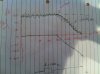
A 1K resistor is a line from left to right through the center of the paper.
A 0.1uf cap is a line from top left to a point at the bottom in the center. "\"
Inductors are lines "/".

Draw a line for every L, C and R in your circuit.

For a 1k resistor and 0.1uf cap low pass filter; draw the lines for the two parts.
At low frequencies (at the left side) the capacitor has no effect so start with the 1k ohm line. Follow along that line until it hits the 0.1uF line then follow along the capacitor line.


Hi Ron,

Your graph there looks quite interesting, so perhaps you can show us an example of using your graph with say two low pass filters connected one after the other so the second one filters the output of the first one (i believe this is called cascade?).
 
Hi foudalnoor,
For reference this image is the LTSpice plot for the 3 circuits, for comparison.

Nice plots !

Foualdanoor, if you compare eric's plots with all the calculations please consider that the simulation results are given as "frequency f" in Hz and not as w=2Pi*f.
More than that, by drawing appropriate asymptotes to the left and to the right part of the magnitude lines you (hopefully) will identify both cross-over points at the w-axis (identical to the poles) that I have mentioned before in my earlier postings.
Now - imagine you only have these asymptotic lines (as we have discussed before), it will be not a problem to smoothly draw the approximate magnitude response using these asymptotes as guidelines.
 
Last edited:
Using information from post #20 by Eric
Solve for output 3.

Look at the low pass filter R6, C5. Draw on the 10k 1nF lines. They intersect at about 16khz. This filter is flat below 10khz (0db) and is -3db at 16khz and slopes down above that.

Look at C4, R5 high pass filter. The filter is flat above at high frequency (gain of 0db). Start at the right side this time and trace along the 10k line until you hit the 100nF line then follow it upward. In this case attenuation us upward. At the right side of the paper the capacitor is very close to 0 ohms. At the intersection point the cap is 10k and the gain is .5 (1/2). As you move to the left the cap impedance goes up causing a smaller gain. At 16hz the cap is about 100k and you have about a 10:1 divider. (about...this is a analog computer)

If you combine the two lines you get a gain of 1 (0db) in the center with -3db points at 160hz and 16khz.

_____________________________________________________
To solve for output 1:
At DC the gain is a function of R1, R2. The capacitor is open. If there were inductors they would be closed (0 ohms).
As we go up in frequency C1 starts to effect R1. This happens where Z of C1= R1 or where the 100k and 1nF line cross. So at 1400hz the gain increases 3db from the DC value.

The gain can not increase above 0db. This circuit will have a gain of 0db at very high frequencies. At the point where the 1nF and 10k line cross the gain is -3db. Above that the gain is 0db.

Looking at this from right to left. At high frequencies the gain is 0db. At 16khz the gain is -3db and heading down. At 1400hz the gain is 3db above the DC gain set by the resistor divider.

_________________________________________________
In school they are looking for answers like 1.5923khz. In real life the resistors are +/-5% and the caps are +/-10% and the impedance of the signal source and the load effect the plot. Also resistors have capacitance and inductance and capacitors have resistance and inductance. With the graph paper you can get the general idea.

To plot the resonant frequency of a CL simply note the point where the two lines cross. The impedance, is capacitive on one side of resonance and inductive on the other side and very much follows the /\ shape of the two lines. At resonance the impedance is "open".
 
Hi,

Oh wow a passive RC filter with a gain of 60db! I love it :)
You might want to included what we sometimes call a 'sanity check' just to make sure you have something reasonable. I mention this because a 60db gain in a passive low pass filter is just not ever going to happen. I cant stress this enough. Once you have the solution, go over it briefly to see if you spot anything that looks like it wont work or is off by a large amount. Maybe it takes time to learn this kind of thing but it's worth thinking about.

You were going pretty good there, with your low pass example. You came up with:
Hs=1/(sRC+1)

and then you divided top and bottom by RC:
Hs=(1/RC)/(s+1/RC)

and you reasoned that you have a pole at 1/RC (of course you know this is really -1/RC). You did very well there.
But now you KEPT that form to figure out the gain, so you of course got the gain 1/RC.
BUT, in the previous discussion, we had to get the equation into the form with the factors (s*tau+1) in order to find the gain K. For some reason you skipped this step and that's how you got the gain of 1/RC, which of course isnt right.
Getting back into the s*tau+1 factors form, we have again:
Hs=1/(sRC+1)
with tau=RC. Now the only thing left in the numerator is the '1', so the gain K is equal to 1.
So try to remember which form is which, and that you need the transfer function in the s*tau+1 factors form to get the gain to stand alone in the numerator.

Haha, yeah I actually don't know why I did that now that you mention it. I forgot that the only reason we change the form is to get the value of w for the pole..

We have a pole at w=1000Hz (so -20dB/dec from that point), before that we have a constant gain of 1 since it was already in the correct form and K = 1. 20log(1) = 0. so actually it would be the same plot, olly shifted dhown from 60dB to 0dB as shown on the attached picture.

You have to remember that I don't really have much experience with using these plots, so the values don't mean too much to me...
 

Attachments

  • photo (1).JPG
    photo (1).JPG
    2.4 MB · Views: 236
Last edited:
Hi,

It appears that you were trying to do the first one (C=1nf, R1=100k, R2=10k) so we'll do that one first. You'll want to note that the zero and the pole cause opposite sign slopes, one +20db/decade and the other -20db/decade.

The transfer function Hs is:
Hs=(s*C*R1*R2+R2)/(s*C*R1*R2+R2+R1)

At zero frequency the gain K is equal to:
K=R2/(R1+R2)

and dividing numerator and denominator by C*R1*R2 we get:
Numerator: N=1/(C*R1)+s
Denominator: D=1/(C*R2)+1/(C*R1)+s

So we have constant gain:
K=1/11

and the numerator is:
N=s+10000

and the denominator is:
D=s+110000

Thus we have a zero at w=10k and a pole at w=110k, and constant gain -21db.

The two frequencies are 10k and 110k, so we start out at w=0 with the constant gain of -21db which is a straight horizontal line (like you have drawn) and at the frequency of 10k we have a zero so we get a slope of +20db/decade starting at 10k. This continues until we reach 110k and there we have another frequency of 110k which is a pole so we get a slope of -20db/decade starting at 110k, and this added to the previous slope means we again get a line with a slope of 0 which is a horizontal line.

So the plot looks like a horizontal line at -21db that goes from w=0 to w=10k, then slopes upward at +20db/decade, then at 110k it becomes a horizontal line again. Since the slope of the upward line is +20db/decade and it starts at -21db and goes from 10k to 110k, that means it goes upward about +22db and this means we end up at +1db, but the horizontal portion from there is around 0db because since the cap conducts much more than the 10k resistor at infinite frequency, the response is clearly 0db above w=110k. Note that since the distance from the 10k to 110k is really 1.1 decades, we would multiply 20db times 1.1 and get 22db as the rise so this would lead us to +1db rather than 0db. But the quick check with the cap and 10k resistor shows this to really be 0db. So we've corrected this a little by doing that.

Also note that when you get a pole after a zero it cancels out the slope of the zero because the pole has the exact opposite slope as the zero.


So the plot looks like this:
Code:
   0                 ------------------
                    /
                   /
                  /
                 /
 -21  -----------
      0        10k  110k              +inf

Now regarding this post. How did you re-arrange the transfer function to get it into the correct form in order to see K clearly? it seems like you just checked what happens when w=0 and then got K somehow...

I cant seem to re-arrange the transfer function of this particular example into the form shown.

I can get this far:

Vo/Vin = R2/(R2+(R1*1/Cs)/(R1+1/Cs)) = (R1Cs+1)/((R1Cs+1)+R1/R2) , here I cant remove the R1/R2 term in the numerator.

Clarifying this would help greatly!
 
Also, is the transfer function for the third (bottom circuit) correct: H(s) = RC1s/((RC2s+1)(RC1s+1))?

May I ask you how did you arrive at this expression? Calculation or guess? I don't think that it is correct.
Remark: It would be correct in case of a buffer between both RC elements (decoupling).
 
Last edited:
Hey, fouadalnoor

I am to lazy for calculating the poles in general terms (R, C) - however, perhaps the following can help you:

The transfer function of the third circuit is:

H(s)=sRC1/[1+sR(C1+2C2) + s^2*R^2*C1C2]

and for the given values the poles are: p1=-990 rad/s and p2=-1.01*1E^5 rad7s.

Hint: You also can find both values using the asymptotic lines in the plot provided by ericgibbs.
 
Hi fouad,

For this Hs:
(s*C*R1*R2+R2)/(s*C*R1*R2+R2+R1)

this is in the general form:
(s*a+A)/(s*b+B)

where lower case 'a' or 'b' is the multiplier of s and upper case is the constant.

Now first we'll get s*b+B into the form s*tau2+1 by dividing top and bottom by B. We get:
(1/B)*(s*a+A)/(s*b/B+1)

and so far this is in the form (with tau2=b/B):
(1/B)*(s*a+A)/(s*tau2+1)

Now we work on the s*a+A part by dividing that by A and multiplying the outside by A to keep the equation the same. We get:
(1/B)*A*(s*a/A+1)/(s*tau2+1)

which is in the form:
(1/B)*A*(s*tau1+1)/(s*tau2+1)

and combining the constants we get:
(A/B)*(s*tau1+1)/(s*tau2+1)

Here you can see the two constants out in front. Since A was equal to R2 and B was equal to R1+R2, the constant A/B is equal to:
R2/(R1+R2)

and that is the K constant.

You'll note that if you evaluate Hs at zero frequency, you'll get this same constant.

So the main idea here is when you see a factor like this:
(s*x+X)

you first divide by X and get:
(s*x/X+1)

and to keep the factor the same as when we started we multiply the whole thing by X:
X*(s*x/X+1)

and that is how we get the constant out in front of the factor. Other factors produce other constants, and after we do all the factors we can lump all the constants together to form one constant in the numerator.

Quick example of factor (s*10+5):
step1: (s*10/5+1)
step2: 5*(s*2+1)
and here we have it in the form of K*(s*tau+1).

Note sometimes this will come out a little messy:
factor: (s*R1*C1+R1+R2)
step1: (s*(R1*C1)/(R1+R2)+1)
step2: (R1+R2)*(s*(R1*C1)/(R1+R2)+1)
and here we have K=R1+R2 and tau=(R1*C1)/(R1+R2).


Next circuit...

Unfortunately your transfer function for Hs for the third (bottom) circuit is not correct. If you multiply the denominator out you'll find that it is missing part of a term. That's because that equation looks like it is the result of a high pass and a low pass but with the two circuits isolated for current (in other words there would be an amplifier in between the two sections with a gain of 1 and this is what Winterstone had mentioned too). The correct transfer function was presented by Winterstone, and if you subtract your denominator from his denominator you'll see the difference. When the circuits are isolated like that their impedances dont interact the way they do when they are connected directly together, and so you loose part of a term in the denominator.

It was nice of Eric to post the simulations so you can compare your results to those plots too.
 
Last edited:
Okay, I have now calculated the second circuit and got the same results as MrAl got:

A constant gain of -80dB and two poles at w= 3819 and w=26180.

But, I dont quite know why we had to do the following step:

"First thing we'll do is multiply N and D by the reciprocal of the factor of s^2 which is 1e-8, so we get:

N=10000*s
D=s^2+30000*s+1e8"


When I just use the quadratic equation without dividing through by 1e-8 I get the same result in the denominator (namely the roots -3819 and -26180) but of course the numerator is not affect and thus stays at 1e-4 and hence I get the wrong gain K. Is it a rule that you always have to keep the quadratic equation in the form s^2+bs+c before using the quadratic formula?

Thanks.
 
Last edited:
Hi fouad,

You seem to be having a problem with the gain so lets start with that.

To find the gain you factor the Hs into this form:

[LATEX]
\ \ \ \ H(s)=\frac{K(s\tau_{1}+1)(s\tau_{2}+1)...}{(s\tau_{3}+1)(s\tau_{4}+1)...}
[/LATEX]

If you look at that you'll see that the numerator is factored into terms with s times tau plus 1, and so is the denominator, and when factored like this the constant gain K stands out in the numerator as a single number.

To illustrate this with your next circuit (the one on the right) we start with the transfer function:
Hs=(s*C1*R2)/(s^2*C1*C2*R1*R2+s*C2*R2+s*C1*R2+s*C1*R1+1)

and yes because all the R's are the same and all the C's are the same this simplifies to:
Hs=(s*C*R)/(s^2*C^2*R^2+3*s*C*R+1)

but now we substitute the values for the components R and C and we get:
Hs=(1e-4*s)/(1e-8*s^2+3e-4*s+1)

Now we have numerator:
N=1e-4*s

and denominator:
1e-8*s^2+3e-4*s+1

First thing we'll do is multiply N and D by the reciprocal of the factor of s^2 which is 1e-8, so we get:

N=10000*s
D=s^2+30000*s+1e8

Now we factor D and we get two roots:
r1=-3819.660112501051
r2=-26180.33988749895

What this means is our transfer function can now be written as:
Hs=10000*s/((s-r1)*(s-r2))

(note we subtract the roots not add them to reconstruct the denominator, and since they were negative they now will come out positive)

which numerically is:
Hs=10000*s/((s+3819.660112501051)*(s+26180.33988749895))

From this we can see that we have two poles one at w=3819.660112501051 and one at w=26180.33988749895.

Now we want to get this new Hs into the form shown above with all the tau's in it, so we take the first pole in the denominator and divide that by the negative of the root:
(s+3819.660112501051)/(3819.660112501051)

and this of course gives us:
s/3819.660112501051+1

and you see now that part is in the "s times tau plus 1" form where tau=1/(-r1)=1/3819.660112501051.

But since we divided that by 3819.660112501051 to keep that part of the equation the same we have to also multiply by that, so we get this form for that one part of the denominator:
3819.660112501051*(s/3819.660112501051+1)

Now we have this in the form 1/tau times the "s times tau plus 1" form.

We have another pole, so we do the same thing with that one and we end up with:
26180.33988749895*(s/26180.33988749895+1)

Again note that this is also in the form (1/tau)*(s*tau+1).

Now we put the Hs back together and we have:
10000*s/((3819.660112501051*(s/3819.660112501051+1))*(26180.33988749895*(s/26180.33988749895+1)))

and since we have two constants in the denominator we can lump them together:
10000*s/(3819.660112501051*26180.33988749895*(s/3819.660112501051+1))*(s/26180.33988749895+1))

This is now in the form N/(Ka*Kb*(s*tau1+1)*(s*tau2+1))

so we simply multiply Ka times Kb which is 3819.660112501051*26180.33988749895 and we get a single number:
Ka*Kb=1e8

So now we have:
10000*s/(1e8*(s/3819.660112501051+1)*(s/26180.33988749895+1))

Now all we do is divide top and bottom by that 1e8 and we end up with:
1e-4*s/((s/3819.660112501051+1)*(s/26180.33988749895+1))

This is now in the form: Kn*s/((s*tau1+1)*(s*tau2+1)).

Since there is no additive term in the numerator we're just about done.
Now all we do is:
Kn(db)=20*log10(Kn)=20*log10(1e-4)=20*(-4)=-80db

so the constant gain is -80db.

Also, these results do not seem to look the same as the ones drawn on the graphs by eric. Shouldnt there be a straight line starting at -80dB and then only changing at w=3819 and w = 26180?
 
Hi,

There are a number of ways to do these problems, i just happened to like starting by dividing out the leading coefficient sometimes. There's no rule you have to simplify a quadratic with no coeff of s^2 because the quadratic formula takes that into account too. If you do divide out the leading coeff, you end up with a slightly simpler version of the quadratic formula.

Did you take into account that the graph Eric's plot shows has the running variable of regular frequency f and not angular frequency w? Most of these calculations are done in terms of w not f, so we end up having to convert at some point for some real problems.
 
Last edited:
Hi,

There are a number of ways to do these problems, i just happened to like starting by dividing out the leading coefficient sometimes. There's no rule you have to simplify a quadratic with no coeff of s^2 because the quadratic formula takes that into account too. If you do divide out the leading coeff, you end up with a slightly simpler version of the quadratic formula.

Did you take into account that the graph Eric's plot shows has the running variable of regular frequency f and not angular frequency w? Most of these calculations are done in terms of w not f, so we end up having to convert at some point for some real problems.

Hmm.. well when if I DONT divide by 1e^-8 then I get the following (when using the quadratic equation in the denominator):

H(s)=(1e-4*s)/(1e-8*s^2+3e-4*s+1)= (1e-4*s)/[(s+3819)(s+26180)]

But now when you change it into the appropriate form you will get a different constant since the numerator is still 1e-4s due to the fact that we never divided by 1e-8

so: K = 1e-4/(26180*3819)

but that can't be right... (am I missed something obvious?)
 
Hello,


Sooner or later you have to start thinking for yourself :)
You have to start learning to put two and two together and come up with the right answer. You have plenty of resources in this thread that you can turn to, so you should be able to figure out how to do this now. You also have to learn to check the validity of your results at least to some degree. If you dont do that you wont be able to handle this when there is no one around to ask what to do for every little tiny thing :)

So what you should do is review all the data in this thread, take a minute or two (or more) to think it over, then figure out what to do. I cant keep telling you how to do little things like algebraic manipulation because that varies from problem to problem and you really have to learn that yourself. If you dont know how to factor you probably should have covered that before getting this far, or you should review that. This is nothing more than algebraic and if you follow the guidelines i presented with the illustration (especially the numerical one with all the factoring) then you should be able to solve this now. The idea is to think once in a while, and review some basic algebra.
 
Last edited:
Hello,


Sooner or later you have to start thinking for yourself :)
You have to start learning to put two and two together and come up with the right answer. You have plenty of resources in this thread that you can turn to, so you should be able to figure out how to do this now. You also have to learn to check the validity of your results at least to some degree. If you dont do that you wont be able to handle this when there is no one around to ask what to do for every little tiny thing :)

So what you should do is review all the data in this thread, take a minute or two (or more) to think it over, then figure out what to do. I cant keep telling you how to do little things like algebraic manipulation because that varies from problem to problem and you really have to learn that yourself. If you dont know how to factor you probably should have covered that before getting this far, or you should review that. This is nothing more than algebraic and if you follow the guidelines i presented with the illustration (especially the numerical one with all the factoring) then you should be able to solve this now. The idea is to think once in a while, and review some basic algebra.

Hello,

Yeah I completely understand! My weakest point is probably algebraic manipulations since I understand the concept and do actually know what I am trying to do, its just that sometimes I will be stuck for a while and not see the most obvious manipulation (its obvious when someone points it out hehe). But yeah Thanks for all your help anyway!
 
Okay, I think I figured the algebra out now...

when you use the quadratic formula you have to make sure you take into account the coefficient in the second order term as so:

(1e-8*s^2+3e-4*s+1) ≠ (s+26180)(s+3819)
(1e-8*s^2+3e-4*s+1) = (s+26180)(s+3819)*1e-8

Because even though when using the quadratic formula it takes into account all the coefficients, when writing the equation you still have to add in the coefficient in the s^2 term! (I never actually knew that...)

Thanks! ;)
 
Hi,

I am happy to hear you figured everything out. You know that the more you know about math the easier this other stuff will be, so you might even want to take a refresher course in some math especially maybe precalculus. You'll be so familiar with these math concepts that you'll be able to concentrate more on the matters at hand much better and faster and wont have to keep stumbling over these little details. That way you can enjoy the electrical/electronic parts much more too.
 
Last edited:
Status
Not open for further replies.

New Articles From Microcontroller Tips

Back
Top