PG1995
Active Member
Hi
I'm creating this thread to proceed with the discussion of this block diagram from this thread. In that thread the block diagram was discussed from post #18 to #20. You can also find some related material to the discussion of block diagram between the posts #4 and #17. Thanks.
Now I'm able to get some clearer picture of the diagram. Please note that one of main objective is to understand how a real system is transferred into a block diagram and how the diagram is interpreted.
Note to self: Don't confuse Isc(t) with short circuit current of solar cell.
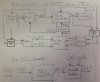
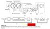
In post #20 of the referenced thread in reply to my question, you said, "That line is labeled i_in(t) which is the input current to the buck converter. The capacitor C_in will be charged by the difference in the i_sc(t) and i_in(t) currents". I don't get it. The line I_in(t) runs from buck converter into Cin, notice the arrow head. Perhaps, this is how it should be interpreted. The behavior of block Cin is dictated by two input variables, i.e. Isc(t) and Iin(t). Here, the behavior is referred to the charging of the system which also dictates the output Vin(t). Also note that the amount of Iin(t) is controlled by the variable s(t). I think that I'm still confused but hopefully you can see where I have it wrong and what is really confusing me.
Note to self: The variable s(t) coming out of PWM block is continuous variable and in reality is a rectangular wave.
In my view it would have been better if arrows haven't been drawn above solar cell and buck converter blocks because they give the impression as if some variable is being input into the blocks. But perhaps that's the way block diagrams are drawn or I'm just reading too much into it!
The digital system which you have drawn at the bottom is in fact a way of looking at what is happening inside the microcontroller. I see the disable detect block as a battery charging algorithm. The value of D[n] is basically determined by the disable detect block. For instance, when a battery is in its first stage of charging, i.e. bulk charging, then disable detect won't play any role as far as I can see and how I conceptualize my project. In other words, disable detect block comes higher in hierarchy of determining the value of D[n] than P&O block.
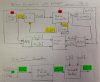
I'm sorry to say this but I don't see any particular feedback loop in the given block diagram. For example, in both these block diagrams, #1 and #2, you can clearly see the feedback loops along with other important blocks. Could you please help me with this? Thank you.
Regards
PG
I'm creating this thread to proceed with the discussion of this block diagram from this thread. In that thread the block diagram was discussed from post #18 to #20. You can also find some related material to the discussion of block diagram between the posts #4 and #17. Thanks.
Now I'm able to get some clearer picture of the diagram. Please note that one of main objective is to understand how a real system is transferred into a block diagram and how the diagram is interpreted.
Note to self: Don't confuse Isc(t) with short circuit current of solar cell.
In post #20 of the referenced thread in reply to my question, you said, "That line is labeled i_in(t) which is the input current to the buck converter. The capacitor C_in will be charged by the difference in the i_sc(t) and i_in(t) currents". I don't get it. The line I_in(t) runs from buck converter into Cin, notice the arrow head. Perhaps, this is how it should be interpreted. The behavior of block Cin is dictated by two input variables, i.e. Isc(t) and Iin(t). Here, the behavior is referred to the charging of the system which also dictates the output Vin(t). Also note that the amount of Iin(t) is controlled by the variable s(t). I think that I'm still confused but hopefully you can see where I have it wrong and what is really confusing me.
Note to self: The variable s(t) coming out of PWM block is continuous variable and in reality is a rectangular wave.
In my view it would have been better if arrows haven't been drawn above solar cell and buck converter blocks because they give the impression as if some variable is being input into the blocks. But perhaps that's the way block diagrams are drawn or I'm just reading too much into it!
The digital system which you have drawn at the bottom is in fact a way of looking at what is happening inside the microcontroller. I see the disable detect block as a battery charging algorithm. The value of D[n] is basically determined by the disable detect block. For instance, when a battery is in its first stage of charging, i.e. bulk charging, then disable detect won't play any role as far as I can see and how I conceptualize my project. In other words, disable detect block comes higher in hierarchy of determining the value of D[n] than P&O block.
I'm sorry to say this but I don't see any particular feedback loop in the given block diagram. For example, in both these block diagrams, #1 and #2, you can clearly see the feedback loops along with other important blocks. Could you please help me with this? Thank you.
Regards
PG
Attachments
Last edited:
") Although as you say this is a non-linear system, I think there should still be a single feedback path from the output to input. I believe that the loop labelled Iin(t) is the main feedback loop. Is it?
Although as you say this is a non-linear system, I think there should still be a single feedback path from the output to input. I believe that the loop labelled Iin(t) is the main feedback loop. Is it?