Continue to Site

Welcome to our site!

Electro Tech is an online community (with over 170,000 members) who enjoy talking about and building electronic circuits, projects and gadgets. To participate you need to register. Registration is free. Click here to register now.

  • Welcome to our site! Electro Tech is an online community (with over 170,000 members) who enjoy talking about and building electronic circuits, projects and gadgets. To participate you need to register. Registration is free. Click here to register now.

Binary input Hex dispaly (7 segment LED)?

Status
Not open for further replies.
By adding some resistors it's possible to control four displays on each 16F628.

This is true if the circuit driving this display unit are capable of both sourcing and sinking the signal (i.e. not open collector) and can handle an extra load of 100 uA.

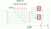
The same pins on the '628 can be connected both to the displays via 220 ohm resistors as well as the outputs from the controlling circuit via 47 Kohm resistors.

The '628 will first set the pins as input, read the incoming signal, calculate the correct bitpattern, set the ports as outputs, output the bitpattern, wait 20 mS and repeat all over again.

This means that the segments on the display can only be changed 50 times per second, but i think that's enough...

The attached picture only shows half of the circuit. It needs to be repeated for portB.

Mike: What program are you using to draw your schematics?

EDIT - I just realized that it's not possible to drive four displays this way using the 628 since the RA5 -port is crippled and can only be used as an input. This input/output sharing thing can be used in other applications to reduce the number of ports required, but for this specific application it's not usable. Sorry.
 

Attachments

  • sameio.gif
    sameio.gif
    14.5 KB · Views: 283
Last edited:
dalmation said:
Wow- thats a lot of work you've put in. I cant say I understand the programming, but I noticed that on the segment table, there is no A-F?

I got myself a book on PIC programming and I look forward to having a better understanding- I really appreciate your help in the mean time.

-Dalmation.

hi,
Look at my version of the program, I did add the 'A,b,c,d,E,F' patterns.
**broken link removed**
You can change to 'HELP?' and many others to suit your project.
 
Last edited:
ericgibbs said:
hi,
Look at my version of the program, I did add the 'A,b,c,d,E,F' patterns.
**broken link removed**
You can change to 'HELP?' and many others to suit your project.


Noticed it straight after my post. Looks excellent, thanks.

Just checked so see if my universal programmer can do pic chips- it can! :)

I'll get some pics and experiment on some veroboard this weekend (missus permitting :)

Thanks again guys.

-Dalmation.
 
matseng said:
By adding some resistors it's possible to control four displays on each 16F628.

Thats pretty impressive, mate. That would save a lot of (precious) space and of course money. I like it.


matseng said:
This is true if the circuit driving this display unit are capable of both sourcing and sinking the signal (i.e. not open collector) and can handle an extra load of 100 uA.

To be honest, I'll need to check if it can sink the signal- I hope so! I'll check the circuit tonight and let you know (fingers crossed). The extra 100uA certainly wont be a problem either way.

matseng said:
The '628 will first set the pins as input, read the incoming signal, calculate the correct bitpattern, set the ports as outputs, output the bitpattern, wait 20 mS and repeat all over again.

I am (for now), in terms of pic program writing, totally dependant on the time people have (incredibly generously!) donated to my cause in this thread- I'm deeply impressed. A program has been written that does 2 displays per pic, and I'm gonna play with that. If anyone can write one to suit your method, then great, otherwise I'll use it as an incentive to learn more on the subject- so far I can make led's flash on and off and change the timing- early days!:D

matseng said:
This means that the segments on the display can only be changed 50 times per second, but i think that's enough...

I believe 50Hz is perfectly adequate for led displays, so that should be fine.


I'm off to look up some space saving resistor arrays to keep within my pcb outline.

Once again- THANKS!!!!
 
I'm sorry. I have to take back my idea since I just realized that it's not possible to use the RA5 -port as an output as it is crippled on most of the PICs and can only be used as an input.

This input/output sharing thing can be used in other applications to reduce the number of ports required, but for this specific application it's not usable.
 
matseng said:
I'm sorry. I have to take back my idea since I just realized that it's not possible to use the RA5 -port as an output as it is crippled on most of the PICs and can only be used as an input.

This input/output sharing thing can be used in other applications to reduce the number of ports required, but for this specific application it's not usable.
hi mats,

Good try, but isnt Bit 7 going have problems with trying to register a high input, its going to be clamped about 0.7V with T1 base/emitter junction.

EDIT: in fact having had a better look at the dwg, all the inputs would have the same problem
 
Last edited:
Eric, you have a point there, I forgot about the transistor there, but by using transistors with a decently high gain it will work even there.

What's the problem with the inputs connected to the anodes? I can't think of anything.

I actually whipped up a test of this on my breadboard now. On the ports connected to the anodes it worked beautifully even with a 100K resistor as isolation to the controlling circuit. And by using BC547B transistors, a 22K as the first base resistor, and a 2.2K as the second it registered by input through a 2.2 K from the controlling circuit.

So the load of the controlling circuits highest bit will be considerably higher (2.3 mA) , but still within a normal range for most ic's.

However, all of this is of no use for the thread creator since the reset port pin is input-only on the PICs.
 
matseng said:
Eric, you have a point there, I forgot about the transistor there, but by using transistors with a decently high gain it will work even there.

What's the problem with the inputs connected to the anodes? I can't think of anything.

I actually whipped up a test of this on my breadboard now. On the ports connected to the anodes it worked beautifully even with a 100K resistor as isolation to the controlling circuit. And by using BC547B transistors, a 22K as the first base resistor, and a 2.2K as the second it registered by input through a 2.2 K from the controlling circuit.

So the load of the controlling circuits highest bit will be considerably higher (2.3 mA) , but still within a normal range for most ic's.

However, all of this is of no use for the thread creator since the reset port pin is input-only on the PICs.

hi mats,
I would be interested to see the results of your trials, when complete, if thats ok.
I did consider using N Mosfets 2N7000 in place of the transistors, I too will try variations, let you know outcome.
 
dalmation said:
Wow- thats a lot of work you've put in. I cant say I understand the programming, but I noticed that on the segment table, there is no A-F?
I think you've figured out that you want to use the schematic and code for Eric's design. My scheme was/is unnecessarily complicated for a two digit display.

Good luck. Have fun. Mike
 
I have enough now to make a prototype circuit.

I'd like to thank you all for all the high quality help you've given me.

It would have been very easy for you to say.. ."use a pic chip- work it out" but th eamount of effort thats been put in is impressive.

I'll post again when I've made my prototype and I'll let you know how I get on (actualy- I'll probably post the full schematic before making my prototype- in case I've missed something obvious:rolleyes: )

Thanks again- I really appreciate your time.

-DAlmation.
 
Thank you for the kind words but after a few years playing with PICs it was just a simple and fun exercise and really didn't take much time. I suspect Eric (ericgibbs) would agree?

Actually, in some spare time early this morning I wrote two new versions of the 16F628A firmware for Eric's hardware design because I suspect there may be some subtle problem(s) using a very high refresh rate with the display.

Both versions (below) refresh the display at 62.5 Hz. One version uses interrupts and the other version uses a delay routine and display loop in Main much like Eric's software example.

Have fun and please let us know how it turns out.

Mike

erics-4477-ic-png.14391

<corrected errors updated program listings 29-Sep-07>
 

Attachments

  • Forum 4477 IC v1.asm
    8.7 KB · Views: 248
  • Forum 4477 IC v2.asm
    8.2 KB · Views: 216
Last edited:
Mike said:
Thank you for the kind words but after a few years playing with PICs it was just a simple and fun exercise and really didn't take much time. I suspect Eric (ericgibbs) would agree?

Actually, in some spare time early this morning I wrote two new versions of the 16F628A firmware for Eric's hardware design because I suspect there may be some subtle problem(s) using a very high refresh rate with the display.

Both versions (below) refresh the display at 62.5 Hz. One version uses interrupts and the other version uses a delay routine and display loop in Main much like Eric's software example.

Have fun and please let us know how it turns out.

Mike

**broken link removed**

hi Mike,
I agree regarding the inter digit delay time.

BTW, you can upload *.asm files now.

Regards
 
Okay- 4 quick questions before I prototype...

1) I ordered some 16F628A chips for the prototype, but they have sent me 16F628 chips (no A) instead. Will that be okay? I'm guessing it will, but I just need to change the model number at the top of the ASM file? Confirm?


2) the resistors on the base of the transistors... 1K:eek:hm: sound about right?


3) with a binary input of "0001" (=HEX01), is the "1" the LSB or the MSB? I can figure it out soon enough with the prototype, but it doesnt hurt to ask.

4) The chip should run okay at 3.3V, right? Datasheet says no prob, so I'm assuming yes.

Thanks again.

-DAlmation.
 
Last edited:
dalmation said:
Okay- 4 quick questions before I prototype...

1) I ordered some 16F628A chips for the prototype, but they have sent me 16F628 chips (no A) instead. Will that be okay? I'm guessing it will, but I just need to change the model number at the top of the ASM file? Confirm?
The *.cfg are different, but I will have to confirm if significant.

edited: COLOR]

2) the resistors on the base of the transistors... 1K:eek:hm: sound about right?
No, at 3.3V you should have a resistor that drives the digit select transistor
harder, say 220R, this should be OK.


3) with a binary input of "0001" (=HEX01), is the "1" the LSB or the MSB? I can figure it out soon enough with the prototype, but it doesnt hurt to ask.
Its the LSB.
Its conventional to start with the lsb on the right, same as ordinary arithmetic, h, t, u.


4) The chip should run okay at 3.3V, right? Datasheet says no prob, so I'm assuming yes.

Thats what the data sheet says.

Thanks again.

-DAlmation.


Hi,
I will check re internal osc.

EDIT:Read datasheet section 14.2.6 ref the internal osc, notes mention +5V?
 
Last edited:
thanks.
Hopefully it just means the oscillator will possible be slightly different than 4mhz if there is less voltage. I guess I'll find out soon enough:eek:

There is probably a 5V supply I can pinch from somewhere else on the main circuit, but that will be a last resort. The 3.3V supply is available on the same socket as the binary outputs.

There is also an external clock pulse available on the same connector as the binary outputs, I'm unsure of the frequency (i'll check)- if it comes to it, I suppose I could use that to synchronise all 4 pic chips and just use 2 (more powerful) transistors to switch all the displays, rather than 2 per display.

- Anyways- I'll try it with the 3.3V and hopefully it will be forgiving enough.

Still annoyed I got wrong chips sent- but too eager to experiment rather than sending them back:D

-DAlmation.
 
Last edited:
dalmation said:
thanks.
Hopefully it just means the oscillator will possible be slightly different than 4mhz if there is less voltage. I guess I'll find out soon enough:eek:
I think its indicating that it will not oscillate.

There is also an external clock pulse available on the same connector as the binary outputs, I'm unsure of the frequency (i'll check)- if it comes to it, I suppose I could use that to synchronise all 4 pic chips and just use 2 (more powerful) transistors to switch all the displays, rather than 2 per display.
I would guess that trying to sync 4 PIC's is a no,no.

- Anyways- I'll try it with the 3.3V and hopefully it will be forgiving enough.

Still annoyed I got wrong chips sent- but too eager to experiment rather than sending them back:D
I know exactly what you mean

-DAlmation.

hi,
Lets know how it goes:)
 
Okay- I have made a prototype on veroboard.

Mixed results... Here's what I learned...

- The datasheet i got with my led displays has incorrect pinout:eek:

-I got the forumV1.asm to work, but the forumV2.asm gave no sign of life on the prototype.
Both had a minor mistake, making the character "C" be displayed as "E". Easily sorted- it was the only section of code I totally understood :)

-The pic16f628A does NOT operate <4.0Vdc (despite the datasheet 3-6V claim).

-My input pins were fine in logic state 1, but at logic 0, they were just floating and the output display was going nuts. To fix this, I had to tie all input pins to ground with 10M:eek:hm: resistors. This kept the pins at zero whilt easily allowing a 1. Means an extra 32 surface mount resistors- I'll need to find room for them:eek:

Questions

When calculating the resistor value for the LED segments- do I take into account the ~1.2V drop accress the transistor?

How do I calculate the resistor values for the base of the transistors? I used 200:eek:hm: , but I will be using 5Vdc supply now instead of 3.3V:(


Thanks again.

-Dalmation
 
Last edited:
dalmation said:
Questions

When calculating the resistor value for the LED segments- do I take into account the ~1.2V drop accress the transistor?

The Vdp across the transistor should be about 0.1/0.2V!, the drop across the LED's is about 1.5V,
you take the Vled drop into account.


How do I calculate the resistor values for the base of the transistors? I used 200:eek:hm: , but I will be using 5Vdc supply now instead of 3.3V:(

330R will be OK

Thanks again.

-Dalmation

Hope this helps
 
Thanks.
I will try the new resistor values tonight. I noticed the 2nd digit 'bleeding' accross the 1st display, so I'm pretty sure the 1st transistor is leaking some current through when off. I'll add a resistor to ground from the base (~10-20x value of the base resistor) I'll choose a transistor I can always get supplies of and I will calculate exact values as well.

Its really coming together here- I'll post a couple of pictures later as well.

Thanks

-DAl.
 
Happy to hear you're making progress. I will correct segment tables and look for problem in the v2 program and post corrections in a few days.

Have fun. Mike...
 
Status
Not open for further replies.

New Articles From Microcontroller Tips

Back
Top