Electro Tech is an online community (with over 170,000 members) who enjoy talking about and building electronic circuits, projects and gadgets. To participate you need to register. Registration is free. Click here to register now.
Welcome to our site! Electro Tech is an online community (with over 170,000 members) who enjoy talking about and building electronic circuits, projects and gadgets. To participate you need to register. Registration is free. Click here to register now.
I was looking over the circuit diagram, and I'm a bit confused...
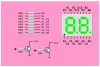
Here is an edited diagram and the pinout for the pic processor...
Heres what I dont get...
The pic has 15 i/o pins, but it appears I need 17 i/o pins:
8 inputs for the binary bits.
7 outputs for the led segments and
2 outputs to switch between the 2 digits.
Am I missing something there?
Also, there are 8 resistors going from the pic chip to the display? is that just a mistake or am I missing something there too (I thought there should only be 7 as I dont need a decimal point).
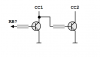
You are not being daft. You have however miscounted the I/O on the pic, it's got 16 I/O lines. As you rightly point out, it appears that you need 17 I/O pins, this is because of the way charlieplexing works. If port B is used to drive the display then it is connected so that bits 2 to 7 go to 6 of the display segments and bit 0 goes to both the unconnected segment on display 1 and display 2's common transistor. Bit 1 goes to the unconnected segment on display 2 and display 1's common transistor.
It might help if you google charlieplexing. Although, the above is not strictly charlieplexing (edit, according to wiki, the above is exactly charlieplexing).
If I understand you correctly- there is no way the circuit will function with only 16 i/o pins- I need 17 pins or a different circuit? Is that correct?
Is it is, could I make it work if I replaced the two transistors with 1 component- some form of solid state switch (functioning like a relay, toggling the power from one digit to the other, depending on input being high or low)- all synchronised with the display i/o pins outputting the 2 different characters.
No, it will work fine with 16 I/O pins. Google charlieplexing and it should make more sense. Having read what I posted above I can understand your confusion, I should have stated it more clearly.
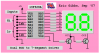
The Charlieplexed display uses 8 pins for both segments and columns. Just imagine we're using the first two of the eight displays shown in the graphic below.
Eric (Ericgibbs) contacted me off list and he's got a much simpler and more elegant solution that doesn't involve the screwy Charlieplexed display wiring and code. His method uses your suggestion for using 1 pin to drive the common cathodes on both displays.
You've got a few lines of code that aren't really doing anything. Other than that your logic is fine.
I would make it a little tighter and simpler but that's just a style difference. In the example below the basic logic and function are unchanged, except for (1) the loop time is constant for either digit now, and (2) digit segment data and the digit select bit are written at the same time to prevent image blur or smear.
Code:
;
;  variables
;
Dig_Sel equ     0x70            ; bit 7 is used to select digit
Temp    equ     0x71            ;
;
        org     0x0000
Reset
        clrf    STATUS          ; force bank 0
        movlw   h'07'           ;
        movwf   CMCON           ; turn comparator off
        bsf     STATUS,RP0      ; bank 1
        movlw   h'FF'           ;
        movwf   TRISA           ; make Port A all inputs
        movlw   h'00'           ;
        movwf   TRISB           ; make Port B all outputs
        bcf     STATUS,RP0      ; bank 0
        clrf    Dig_Sel         ; init Digit Select (B7 = 0)
Loop
        movf    PORTA,W         ; get Lo input in b3..b0
        btfsc   Dig_Sel,7       ; low digit? yes, skip, else
        swapf   PORTA,W         ; get Hi input in b3..b0
        call    SegData         ; get segment data
        iorwf   Dig_Sel,W       ; pick up digit select bit (b7)
        movwf   PORTB           ; update display

        movlw   b'10000000'     ; digit select bit mask
        xorwf   Dig_Sel,F       ; toggle b7 digit select bit
        goto    Loop            ;
Do you think there might be any problem scanning the display at such a high frequency (something like 20-KHz)? Anyone?
hi Mike,
That looks fine, much more compact.
I will have to get a couple of 628A and give it a try in real time, as we both know simulators do have limitations.
I did consider the high refresh rate [20KHz] but the spec on my FND357 LED's indicated it would be OK. It would be interesting if one of the OP's, who have been asking for bin2hex drivers gave it a shot. For about $2 its much more cost effective and has a smaller on board footprint than discrete ic's.
If the refresh rate is too fast for some LED's a short inter LED delay would be easy to implement.
It would be interesting if one of the OP's, who have been asking for bin2hex drivers gave it a shot. For about $2 its much more cost effective and has a smaller on board footprint than discrete ic's.
I agree. It might also be helpful for those chaps building discrete logic clocks but the design does have some limitations. For example, it almost seems you'd need two versions, one with leading zero suppression, and one without, and I don't see an easy way to implement brightness control.
I agree. Here's a simple low overhead 8 bit DelayUS() sub-system (macro and subroutine) that could be used by those interested in experimenting with inter-digit delay time;
Code:
        radix   dec
;******************************************************************
;                                                                 *
;  DelayUS(8..1031), 4 MHz clock      Mike McLaren, K8LH, Jun'07  *
;                                                                 *
;  requires the use of constant operands known at assembly time!  *
;                                                                 *
;  7 words, 0 ram variables, 14 bit core                          *
;                            ^^^^^^^^^^^                          *
;  the macro generates 2 instructions;                            *
;                                                                 *
DelayUS macro   delay           ; parameter 8..1031
        movlw   delay/4-1
        call    Delay4Tcy-(delay%4)
        endm
;                                                                 *
;  code for simulation testing;                                   *
;                                                                 *
SimTest DelayUS(1000)           ; delay 'n' usecs
        nop                     ; put simulator break point here
;                                                                 *
;******************************************************************
        nop                     ; entry point for (delay%4) == 3  |B0
        nop                     ; entry point for (delay%4) == 2  |B0
        nop                     ; entry point for (delay%4) == 1  |B0
Delay4Tcy
        addlw   -1              ; entry point for (delay%4) == 0  |B0
        skpz                    ;                                 |B0
        goto    Delay4Tcy       ;                                 |B0
        return                  ;                                 |B0
;******************************************************************
You might use it within the driver loop like this;
Code:
Loop
        movf    PORTA,W         ; get Lo input in b3..b0
        btfsc   Dig_Sel,7       ; low digit? yes, skip, else
        swapf   PORTA,W         ; get Hi input in b3..b0
        call    SegData         ; get segment data
        iorwf   Dig_Sel,W       ; pick up digit select bit (b7)
        movwf   PORTB           ; update display
        DelayUS(1000)           ; delay 1 msec
        movlw   b'10000000'     ; digit select bit mask
        xorwf   Dig_Sel,F       ; toggle b7 digit select bit
        goto    Loop            ;
Eric (Ericgibbs) contacted me off list and he's got a much simpler and more elegant solution that doesn't involve the screwy Charlieplexed display wiring and code. His method uses your suggestion for using 1 pin to drive the common cathodes on both displays.
This site uses cookies to help personalise content, tailor your experience and to keep you logged in if you register.
By continuing to use this site, you are consenting to our use of cookies.