Electro Tech is an online community (with over 170,000 members) who enjoy talking about and building electronic circuits, projects and gadgets. To participate you need to register. Registration is free. Click here to register now.
Welcome to our site! Electro Tech is an online community (with over 170,000 members) who enjoy talking about and building electronic circuits, projects and gadgets. To participate you need to register. Registration is free. Click here to register now.
any bode can help me about bidirectional dc current sensing with 358 or 324 op amp ? need its output read form mcu. i was try on Google , but not get it .
i'm trying to do an amp meter with a shunt
I have need to read 50 amp DC. for inverter.
1- as on load ( when inverter on , now charging
off)
2- as on charging mode (now invereter
off ,charging on )
these reading read with 1 ADC .
not 2 ADC.
Not sure if it's one or two sensors, but I would not bother with the shunt approach. Use one of these: https://www.pololu.com/product/2199 The output is inherently isolated.
Not sure if it's one or two sensors, but I would not bother with the shunt approach. Use one of these: https://www.pololu.com/product/2199 The output is inherently isolated.
You're making it far too complicated - use a single opamp and bias it so zero current gives half voltage out, current one way will increase the voltage, current the other way will decrease it - one opamp, one adc, a little simple maths, no problem.
You're making it far too complicated - use a single opamp and bias it so zero current gives half voltage out, current one way will increase the voltage, current the other way will decrease it - one opamp, one adc, a little simple maths, no problem.
yes sir too complicated ,
when i usedit one by one ADC .is work fine
but when Add 2 pc IN 4148 diAod . its droped 0.350 volt on o\p terminal.
i use reff doc those AN1521 form microchip .
in this Atchment show only 1 part
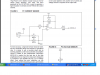
Assume: ADC range is 0 to 1V
Assume:Vref=1V
Want to measure +/- current.
(I think a gain of 100 is too large but)
R12 and R13 (2k and 2k) look like a 1k to 1/2 of Vref. (1k to 0.5V)
The amp has a gain of 100x. So a +/- 5mV signal will make a +/-500mV signal centered around 0.5V.
Assume: ADC range is 0 to 1V
Assume:Vref=1V
Want to measure +/- current.
(I think a gain of 100 is too large but)
R12 and R13 (2k and 2k) look like a 1k to 1/2 of Vref. (1k to 0.5V)
The amp has a gain of 100x. So a +/- 5mV signal will make a +/-500mV signal centered around 0.5V. View attachment 89230
The output of the opamp will be a negative voltage in the cct you provided. The positive reference voltage should be connected to the +ve input of the opamp.
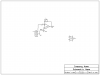
I think it's better to do it as shown in the following circuit. Zero amps gives ~2.5V out, -50 A --> 5 V out and +50 A --> 0 V out. Gain can be changed by changing R1.
I think it's better to do it as shown in the following circuit. Zero amps gives ~2.5V out, -50 A --> 5 V out and +50 A --> 0 V out. Gain can be changed by changing R1. View attachment 89239
whats the EQUATION of this sch ?
Also tell me About v1 & v2. v1 is those voltage , which Are develop here by current flow ?
v2 is reff voltage . I'm right ?
This site uses cookies to help personalise content, tailor your experience and to keep you logged in if you register.
By continuing to use this site, you are consenting to our use of cookies.