2PAC Mafia
Member
Hi guys,
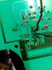
a customer sent me a battery charger manufactured at Italy, I see somebody already replaced a capacitor (C7) and the fuse but not working yet. I see it has a SMD 6 pin component marked as 73B32 or 73832, not sure about that, it´s used for SMPS transformer.
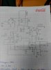
I attach the schematic I made from that part. I find two problems:
First one is about the power to that IC1, as you can see at schematic it should be powered first through a 1M resistor, then a transistor which bypass the power to the IC. OK, this is really strange. If I measure at resistor R8 I have 320V at one side and 0,7V at the other side. I have checked R8, ZD1, Q1, R12, C6, C8 and D1. All the components are good. I found frozen solderings at transistor but that was not solving the problem. In fact, if I power C8 with my power supply power goes into pin 5 from IC1!!! It´s really strange, I measure continuity between upper point from resistor and bottom point to be sure there was contact... I don´t know why I get only 0,7V there.
My second problem is about IC1, when I power it there is not PWM output to switch the transistor, it´s DC output at pin 6, so I think it´s damaged and I´ve been looking for some info about it and I can only find 73832 info, but it´s not in that SMD package so I´m not sure...
a customer sent me a battery charger manufactured at Italy, I see somebody already replaced a capacitor (C7) and the fuse but not working yet. I see it has a SMD 6 pin component marked as 73B32 or 73832, not sure about that, it´s used for SMPS transformer.
I attach the schematic I made from that part. I find two problems:
First one is about the power to that IC1, as you can see at schematic it should be powered first through a 1M resistor, then a transistor which bypass the power to the IC. OK, this is really strange. If I measure at resistor R8 I have 320V at one side and 0,7V at the other side. I have checked R8, ZD1, Q1, R12, C6, C8 and D1. All the components are good. I found frozen solderings at transistor but that was not solving the problem. In fact, if I power C8 with my power supply power goes into pin 5 from IC1!!! It´s really strange, I measure continuity between upper point from resistor and bottom point to be sure there was contact... I don´t know why I get only 0,7V there.
My second problem is about IC1, when I power it there is not PWM output to switch the transistor, it´s DC output at pin 6, so I think it´s damaged and I´ve been looking for some info about it and I can only find 73832 info, but it´s not in that SMD package so I´m not sure...