Continue to Site

Welcome to our site!

Electro Tech is an online community (with over 170,000 members) who enjoy talking about and building electronic circuits, projects and gadgets. To participate you need to register. Registration is free. Click here to register now.

  • Welcome to our site! Electro Tech is an online community (with over 170,000 members) who enjoy talking about and building electronic circuits, projects and gadgets. To participate you need to register. Registration is free. Click here to register now.

Batteries & Chargers

Status
Not open for further replies.
but ohms law says i = v / r which would be
5.18v / 1.2K (1200) = 0.0041mA

Which should be 4mA why do i read 2.7mA ?


EDIT:
I see without the led its 4.3mA. How would i account for led?

And when i add led why is it showing less current?

Hi,
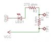
Whats the voltage drop across the LED.?
You have to subtract that voltage from the Vcc in order to calculate the current in the circuit.:)

(5.18v-Vled) / 1.2K (1200) = 0.0027

example:
(5.18-1.6)/1200 = 0.0029A
 
Last edited:
oh ok its 3.29v .after led drops it.

3.29 / 1200 = 0.00274
2.74mA which is good.

(LED Drops 1.89 and voltage was 5.18 so new voltage after drop is 3.29)
 
Last edited:
oh ok its 3.29v .after led drops it.

3.29 / 1200 = 0.00274
2.74mA which is good.

(LED Drops 1.89 and voltage was 5.18 so new voltage after drop is 3.29)

hi,
I have just added an example to my last post.
If you replace my guestimate of 1.6V with your 1.89V. you are spot on..
 
Last edited:
ok now the issue lol for some reason i try to measure the current from glcd and it wont work. The screen doesnt go on when i try to close circuit with meter.
 
hero:
I didnt calc for both just showing the info i calc'd for 200mA for max since glcd uses like 11 pins thats 25mA * 11 (or max) but i am most likely wrong since i am indeed a noob to this lol
If your GLCD uses 25mA per pin that's 25*11 = 265mA so your microcontroller will be cooked.

I doubt it uses that much current on the input pins, they'll probably be CMOS inputs which barely use any current you so can probably safely disregard it.

So what your telling me is that a components like LEDs for example can source a max of 20mA. It depends on what i give it? so if i want i can send it only 5-10mA and brightness with vary i assume but is that how it works. lol (i dont know how i got through all this without knowing this either lol.)
That's true, the absolute maximum current for a typical 5mm LED is normally about 20mA but it's better to go lower than this as the LEDs will last longer. Normally the brightness of LEDs is specified at 10mA which is fine for most applications, especially if you want to save power.

For the "What do you mean 15mA" look at attachment. I will try measuring how much actual current the glcd draws at this moment.
That's fine, just add the figure on.

As far as charging the batteries is concerned, you can probably use the MCU to help you with that. Just use a current limiting resistor to charge them at about 750mA. The cell voltage will gradually rise to about 1.6V before rapidly tapering off to about 1.5V; you could use a comparator or ADC to detect this voltage change. After this you limit the current to around 60mA which can easilly be done by connecting a resistor across the transistor used to switch the batteries. This should charge the batteries in around four hours.

You don't have to monitor the voltage across all the cells, the one nearst the 0V rail will do. It's also better to switch the + side of the batteries so you're not measureing the transistor's saturation voltage on top of the bottom cell's voltage.

It's also a good idea to add a thermal fuse or thermistor so you can disconnet the batteries in case they get too hot.
 
ok now the issue lol for some reason i try to measure the current from glcd and it wont work. The screen doesnt go on when i try to close circuit with meter.

hi,
You should set the ammeter for the highest range possible, example 1amp.

If you set it at say 100mA you will most likely drop all the voltage across the ammeter.! and the GLCD will not run.

Remember: measure the current in the high side +V lead.
 
Last edited:
An LED is bright when you limit its current to 20mA. A PIC can supply 25mA safely but without a current-limiting resistor the LED and the PIC might burn out. Maybe your PIC is not driving an LED then its current is very low.

I assume that the GLCD screen is an LCD screen that probably uses very low current from the PIC. It uses 12.2V for "LC" whatever that is. Maybe the LC is the square-wave drive to the backplane.
The screen has LEDs either for a backlight or for sensing your finger position.
 
ok Erric. I disconnected the +v and closed the circuit from v+ supply to +V i disconnected and i measure .003A (3mA). Would that be correct? Below is a image of what i did.

gcurr-jpg.21385


EDIT: I forgot 1 wire lol i fixed (re-read above)

I did it straight to power like vin is closed by amp meter and its shows 160mA
 

Attachments

  • gcurr.jpg
    gcurr.jpg
    201 KB · Views: 284
Last edited:
hi,
That looks better.

What about +/-Vled you dont show a series resistor.?

Also whats the voltage on the circuit side of the ammeter.?
 
Last edited:
i have a resistor there i just didnt want to make a schematic lol so i copied this from Mikro...

Its a 8 ohm.

At this moment i cant find my leads to the other meter i have so cant check with 1st meter on.

EDIT FOUND THEM!
 
Last edited:
Ok:
AMP Meter = .003A (3mA)
Volt. Meter = 5.09v (testing from gnd to circuit side of amp meter)

EDIT:
I have to step out to pharmacy and run some errands. Ill be back in like a hour. Hope to cya later.
 
Last edited:
Ok:
AMP Meter = .003A (3mA)
Volt. Meter = 5.09v (testing from gnd to circuit side of amp meter)

EDIT:
I have to step out to pharmacy and run some errands. Ill be back in like a hour. Hope to cya later.

hi,
I would expect the GLCD on its own to be a 2 or 3milliamps,[ as you have measured] thats not including the 8R and Vled backlight current or the PIC shown in the picture.

Do the same current test for the 8R and +V backlight and repeat it for the PIC.

Adding all these different currents should give a total current value.
Once you have that total current value, you can start thinking about batteries.

If you want to maximise battery life, you only need the backlight when someone is viewing the GLCD.!
A simple push button for the B/L would be OK.
 
Last edited:
Current For Project:

GLCD = 3mA
GLCD_LED = 143mA
Pic (uC) = 25mA

Total = 171mA

As of right now there are no leds on breadboard.
So to calc:

2500 / 171 = 14.61xx (14 Hours)

EDIT: If LED (backlight) is on when needed. Lets say 30% of the time (43 mA) that would make it 71mA total

2500 / 71 = 35 Hours? lol
 
Last edited:
Now knowing this ohms law rules! I finally get it lol.

if i have a 5v supply and want to give a led 10mA i just

5v - 1.9v(typical led drop (for me)) = 3.1v

3.1 / .01A = 310 ohm

310 ohm resistor would be needed to send 10mA to the led. Am i right?
 
Last edited:
Now knowing this ohms law rules! I finally get it lol.

if i have a 5v supply and want to give a led 10mA i just

5v - 1.9v(typical led drop (for me)) = 3.1v

3.1 / .01A = 310 ohm

310 ohm resistor would be needed to send 10mA to the led. Am i right?

hi atom,
Thats looks good to me.:)
Same applies for two or more LED's in series,,, take the sum of the Vled drops from the +Vsupply and divide by the current thru the LED chain.

Always allow for the different forward voltage drop across different 'coloured' LED's

3.1 / .01A = 310 ohm
For this you choose the nearest preferred value say, 270R or 330R

EDIT: do you have a 1R0 [1ohm] resistor on the shelf, also does your DVM have a 200mV arnge.?
 
Last edited:
Now you can plan a battery.
Where is 5V coming from?
If it is a 7805 voltage regulator then it needs a minimum input of 7V.
Six 1.2v cells produce 7.2V when charged but drop to only 6V when run down. Maybe use 7 cells.
 
Or a low dropout regulator.
 
Status
Not open for further replies.

Latest threads

New Articles From Microcontroller Tips

Back
Top