Continue to Site

Welcome to our site!

Electro Tech is an online community (with over 170,000 members) who enjoy talking about and building electronic circuits, projects and gadgets. To participate you need to register. Registration is free. Click here to register now.

  • Welcome to our site! Electro Tech is an online community (with over 170,000 members) who enjoy talking about and building electronic circuits, projects and gadgets. To participate you need to register. Registration is free. Click here to register now.

Bass preamp schematic help needed

Status
Not open for further replies.

Skywalker83

New Member
Ok here is a passive/active set up im planning on making as an internal preramp and EQ for my bass. The passive section features a pickup blend pot, tone and volume. The active section (powered by a 9V PP3 battery) features, 3 band EQ with Mid sweep and volume.

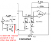
I'm having a bit of trouble working out the input stage. I'd like the first op amp set up so that the input gain can be adjusted via a trim pot.

Also im not sure where the two leads from the battery section go to...

Any help much appreciated!

**broken link removed**
 
The first opamp must be a non-inverting type that has a high input inpedance. Its gain is adjusted by the value of its feedback resistor.

The second opamp is wrong. Its input pin 5 should be connected to the junction of R1 and R2, not ground.
 
Ok here's the revision with the 2nd op amp inputs fixed.

would the current Opamp be suitable or would i need a different model of op amp for the input?

Do you know of any examples of the trim pot gain setup with an opamp that would help me?

Also where do the 2 leads from the battery circuit go to?

**broken link removed**
 
Instead of connecting the non-inverting input pin 5 of the second opamp to the junction of R1 and R2 as I recommended, now the second opamp has positive feedback and is an oscillator or its output latches high or low.

The dual opamps need to be powered. Look on their datasheet to see where to connect the 9V battery.
 
i found a circuit for a guitar preamp. so i've altered the schematic and added it in at the begining.

Does the second opamp still need to be altered to what was suggested?

is there a combination of the 2 circuits that would work better?

**broken link removed**
 
The second opamp has positive feedback instead of negative feedback so it won't work.
It also has one input connected to ground so it won't work.

The dual opamps need filter capacitors from their pin 8 to ground.
 
Last edited:
If you would be so kind, could you take a moment or two , to stick my diagram into photoshop or something and scribble in the corrections that it needs?
 
The second opamp is corrected here:
 

Attachments

  • bass preamp.PNG
    bass preamp.PNG
    34.6 KB · Views: 2,191
I just noticed another error. The mid-frequency has the opamp's pin 5 grounded.
The 2.7k resistor should be connected to half the supply voltage.
 

Attachments

  • bass preamp2.PNG
    bass preamp2.PNG
    33.6 KB · Views: 954
Thanks again! Should both of these corrected connections go between the 33K and 470K resistors? or after the 470K resistor like the above schematic?

Apart from this, how is it looking?
 
The two 33k resistors and the 47uF capacitor are doing a lot of things, maybe too many things. Usually the circuit has a positive supply and a negative supply then "half the supply voltage" is 0V instead of using two 33k resistors and a 47uF capacitor. Another way to make a "half the supply voltage" is with another opamp.

Try it. If the bass sounds strange or if the circuit oscillates at a low frequency then another opamp is needed to buffer the "half the supply voltage".
 

Attachments

  • bass preamp3.PNG
    bass preamp3.PNG
    27.5 KB · Views: 997
Why did you disconnect the 470k resistor from pin 3 of the first opamp? It biases this opamp at half the supply voltage.

Pin 5 of the second opamp must connect to the junction of the two 33k resistors and the 470k resistor and the 47uF capacitor.
 
Horray! The circuit is finally fixed.

Guess what. The minimum total supply used on the datasheet for the LM833 dual opamp is 10V. Your 9V battery will quickly drop to 7.2V and the opamps might stop working or have distortion.

The newer LM4562 has extremely low distortion and low noise and is also a dual opamp with the same pins. Its minimum total supply is 5V.
The NE5532 is also a low distortion low noise dual opamp with a minimum supply of 6V.
 
i was actually thinking of using TL072 op amps as these seem to be most common. I was having a look earlier.
The TL072 opamps are good for line level audio but have more noise than the lower noise opamps which gives hiss for a mic preamp that has high gain.
The minimum total supply voltage for the TL072 is 7V.
 
Status
Not open for further replies.

Latest threads

Back
Top