Electro Tech is an online community (with over 170,000 members) who enjoy talking about and building electronic circuits, projects and gadgets. To participate you need to register. Registration is free. Click here to register now.
Welcome to our site! Electro Tech is an online community (with over 170,000 members) who enjoy talking about and building electronic circuits, projects and gadgets. To participate you need to register. Registration is free. Click here to register now.
hey Timbo,
On reading this thread I thought you'd like the look of this electronic kit from Jaycar Electronics www.jaycar.com.au and the kit number is kj8236 (retails for $14.95 ) and the instructions kj8237 ($2.00). cheers Bryan
Hi Timbo,
Never mind Duracell. They fired all their engineers up here so I boycott them.
Energizer have excellent products and a really good website. Look-up the details of your battery requirement on their datasheets (click on Technical Info). Don't believe the ma/hr ratings in the chart, they are exaggerated with a 0.8V low-voltage cutoff. Use a more reasonable cutoff voltage of 1.0V or 1.1V on their datasheets instead. Check the ratings of their Lithium AA cells. www.energizer.com
There's no 'general' answer, it depends on each specific case - but, to start with, you don't supply a 'battery power of 6A', you provide a supply with the 'capability to provide 6A' - the load takes as much current as it requires, and is (obviously) totally dependent on the type of load.
Generally you would try and design a project to take account of the different supply possibilities, particularly for a battery powered project, where you need to account for the batteries running low.
I'll explain. I'm playing about with a Thermoelectric module. This specific one requires 9v and 6a to operate at full temperature difference.
I've tried connecting it to 3 aa batteries. I'm unsure of their current values. Heres the question. Let say for argument sake, that the 3 batteries provide in total, 7 amps (lets say). Is this going to blow/damage the TE module, or, is the TE module (load) going to take as much as it needs??
Second question. (I get mixed up between series and parallel connections- so forgive me please)... Lets say I connect up 2 TE modules, in parellel, again, with a 9v and 6a power supply. If connected up in parallel, will they both work of 9v and 6a (i.e. no extra power required). question 3 --- will connecting 2 te modules in the circuit reduce the battery life?
Sorry its basic stuff. I think I know the answers, but would rather experts answered it for me..
I'll explain. I'm playing about with a Thermoelectric module. This specific one requires 9v and 6a to operate at full temperature difference.
I've tried connecting it to 3 aa batteries. I'm unsure of their current values. Heres the question. Let say for argument sake, that the 3 batteries provide in total, 7 amps (lets say). Is this going to blow/damage the TE module, or, is the TE module (load) going to take as much as it needs??
As I mentioned above, a supply doesn't 'supply' a certain amount of current, the amount of current 'taken' from the supply depends ont he load. It's an incredibly simple formula, and it's somethign you MUST know if you are playing with electricity, never mind electronics.
Ohms law: V = I x R
It's highly unlikely that your AA batteries will be able to supply sufficient current anyway, although NiCd or NiMh will be able to for a short time.
Second question. (I get mixed up between series and parallel connections- so forgive me please)... Lets say I connect up 2 TE modules, in parellel, again, with a 9v and 6a power supply. If connected up in parallel, will they both work of 9v and 6a (i.e. no extra power required). question 3 --- will connecting 2 te modules in the circuit reduce the battery life?
As above, you don't have a '6A supply', the load will take what it needs, in this case it will try to take 12A, 6A for each load - if the supply can't provide 12A the voltage will fall, governed by the ohms law formula above (where R is the internal resistance of the battery).
BTW, 6A is a LOT of current to be taking from batteries, you will need large ones (car batteries perhaps?), if you want it to last more than minutes.
Hi Timbo,
Little AA battery cells are 1.5V when new and 3 in series will supply 4.5V at about 100mA or less, or less voltage at a higher current for a very short time.
6A is like a dead short for them, and also 3A which the load will probably draw with the half supply voltage. They will heat-up (for a short time until dead) even more than your thermo-thingy load!
Your load is rated to dissipate 54W (9 X 6). If you apply too much voltage like from a 12V car battery, your load will draw 8A and dissipate 96W. It will overheat and maybe burn-out.
Of course extra power is required from a supply if you connect 2 loads to it in parallel. 6A for the 1st one plus 6A for the 2nd equals 12A drawn from the 9V supply.
in terms of the fading circuit,, i need you help audioguru....originally I had the LED's connected to a 1k resistor...and then to the + or - depending on which pair you take.
I have reduced the resistance to 200 Ohms (which appears to be double than that stated on the original drawing)...the smoothness of the fading seems to have disappeared... it is very inconsistent. .for 1 or 2 fades,,, it is smooth, but then the 3rd fade might be a sudden flash on.. and the same for the next pair.......can you advise me on this.....
Hi Timbo,
It sounds like the voltage of your battery is sagging due to the heavier load caused by reducing the values of the LED current-limiting resistors.
Like I said before, that circuit is very critical for voltages, it might need a regulated supply to remain consistent.
On the LED fading circuits that I design, either the LED's current is varied (so voltage doesn't make any difference), or the LED's ON time is varied with pulse-width-modulation. Both ways work perfectly, then when the battery 's voltage drops to a certain low point, the circuit just stops working completely.
Hi Timbo,
Another thing that would probably keep the LEDs consistent would be to add a 1000uF/16V capacitor across the power supply (battery).
Pulse-Width-Modulation is used to efficiently vary the brightness of lights, the speed of motors and the temp of heaters. Your home light dimmers and my Plants circuit use it, and so does our variable-speed drills and furnaces.
Instead of using a huge, hot (wasteful) variable reostat in series to vary the current, PWM uses a transistor, FET, SCR or Triac as an on-off switch. Since it is either fully on or off, it barely gets warm. It is turned on and off pulsing very quickly so you can't see flickering nor feel vibration. If you want the light to be bright, the motor to be fast and the heater to be hot then have the on part of the pulses the widest. If you want a bit of dimming, the motor slowed or the heater cooled a bit, then reduce the on time of the pulse and increase the off time. If you want the light to be very dim, the motor very slow or the heater just warm, then reduce the on time of the pulse to near minimum and increase the off time to near maximum.
The 1000uF/16V capacitor; should it be connected to each 47k resistor to the ground and supply?
Question: If i were to replace the 9V battery with 4 AA batteries (more/longer current supply Ah's - thats my thinking) the power supply voltage would drop to 6V (or there abouts). Would changing the value of the 47k resistors (ground and supply) balance this out.
Would I use ohms law to calculate the new resistance value?
Hi Timbo,
Just put the 1000uF right across the battery connections of your circuit. Its charge will help hold up the voltage of the sagging battery during higher-current peaks from the LEDs.
That circuit won't work with only 6V, it barely works with 9V. That's the problem that you are having with your low battery voltage.
The output of the opamp is centered at half the supply voltage and ramps up about 1V and down about 1V. So with a 6V supply it would vary from 2V to 4V. But the series LEDs need about 2V each plus the 0.7V for the transistor, and therefore would need about 4.7V from the opamp just to light dimly. 4.7V would never occur.
If you used a 6V supply with only one LED (on each side) then the transistor would need only about 2.7V from the opamp to light dimly. It would work but the LED would abruptly shut-off when the ramping voltage (2V to 4V) decreases lower than about 2.7V.
Voltage is very critical in this circuit.
i've just connected up 6 aa batterys... = 9v... however this has caused the leds to flicker even more..the smooth fading is gone.. the aa's are 800 mA each.. yet this can't be the cause as they only draw as much as they need....
the 1000uF capacitor literally connects between the positive and the negative of the power supply?..
The price of the components are nearly dirt at Jameco, are there any obvious problems that I should look out for??
I'm only just now learning about semi-conductors in college, and would appreciate any thoughts you could give on the subject. I'll be waiting until winter break to build it, I'm just planning ahead.
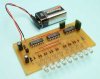
Have wired the circuit on to vari board now- and thats a hole new thing in itself.
The result: The set of pairs from the 2nd side of the op amp (activated by pin 8) work fine. The first set of led pairs only light up, no fading. Even more their illumination has dimmed a little since i first connected it up. I've done something to permantently dim them.
- i have checked and re-checked all components
- Could this half of the op amp be broken?
This site uses cookies to help personalise content, tailor your experience and to keep you logged in if you register.
By continuing to use this site, you are consenting to our use of cookies.