Electro Tech is an online community (with over 170,000 members) who enjoy talking about and building electronic circuits, projects and gadgets. To participate you need to register. Registration is free. Click here to register now.
Welcome to our site! Electro Tech is an online community (with over 170,000 members) who enjoy talking about and building electronic circuits, projects and gadgets. To participate you need to register. Registration is free. Click here to register now.
Trying to figure this out.. to keep it short When you flip the switch it blows the fuse instant.. perhaps the rectifier has failed? Is it common for this to happen?
It's a powered Subwoofer a EV SxA180 with a Class D amp
What I can't remember is how to test the rectifier
Test the rectifier with the diode setting on the meter. Should read about .7V one way between each of the ~ and +, and between the - and ~ (red - black probes), then should read "open" on the reverse (black - red probes).
Problem is you might have a transformer winding making it read 0V, and the big filter caps can throw it off, too. Really need to disconnect that bridge first.
More common than the bridge is a blown driver. These often fail short. Disconnect the speaker, use the same diode check, and see if you get a short to ground or to the supply voltage on the speaker output.
I think I tested it last time with the speaker disconnected and it still blew the fuse.. So are you saying I should take the rectifier out of the circuit to test?
having said that if it indeed the rectifier can I substitute one with a lower Maximum Average Forward Rectified Current 4 Amps compared to the 10A one that's in it now? the reason I ask is it's almost $10 to ship for a $1.46 rectifier from Mouser.
I would suggest removing the rectifier and seeing if the fuse blows then, assuming it doesn't blow, test the rectifier - if it's faulty it will read S/C between at least two of the pins.
I wouldn't worry about the rectifier size, until you've proved it's duff.
It doesn't matter if the speaker is disconnected, if Q10 and Q11 are blown short it will still blow the fuse. Put the meter on diode check and check the output ahead of the relay - L1 and L2 will guide you to that junction.
It doesn't matter if the speaker is disconnected, if Q10 and Q11 are blown short it will still blow the fuse. Put the meter on diode check and check the output ahead of the relay - L1 and L2 will guide you to that junction.
Source and drain - they are actually MOSFETs, the schematic incorrectly shows a FET, emitter and collector are for bipolar. Yes, if you can identify source and drain use those. I was merely suggesting a simple way to locate the common junction between them upstream of that output relay.
Not saying you are wrong or anything but are you sure it's a MOSFET? Do they make any in a TO-92 package? you can just make out in one of my pictures of Q10 & 11 and it for sure is a to-92 package.
**broken link removed**
*edit wait what page are you looking at? hmm.. I was looking at Page 1 Which has Q10 & Q11 both being listed as C1815
And on page 2 I see they have Q10 IRF6215 and Q11 IRF3315
I think this stuff is on the other board since it's two sections.
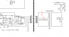
Check that 100V cap at top left of the picture. It looks decidedly cooked (or perhaps that goo is just hot-melt glue?). The transformer seems to have been running hot too, judging by the discolouration of the pcb.
Check that 100V cap at top left of the picture. It looks decidedly cooked (or perhaps that goo is just hot-melt glue?). The transformer seems to have been running hot too, judging by the discolouration of the pcb.
the transformer shown at sch in post #3 is funny in configuration.
the bridge (each of them) appear as full wave.
the trafo doesn't appear to have center tap. the wire leading to ground is shown floating inside the trafo location.The concerned sec is appended.
can I suspect a print mistake or error due to compression?
At times we have condenser blocked dual supplies. but cant take much load.
PS: A sample reply from another site indicated and I quote"Open the cabinet and check the wiring for a loose connection. Also look at the power amp circuit board's load resistor bank. You may have one or two open power resistors."
Ok let me report my findings.. For some reason the internet was not working at the place where the subwoofer was.. anyways.. pretty much everything but Q10B showed open when I tested and this is with them out of circuit.
I'd charge the MOSFET and then check the drain to source and it was still at 0V.
The only one that worked right was Q10
Also with the rectifier works fine.
Anything wrong with the testing? I've never worked on these types of MOSFETS before.. I have them in front of me now at home since I'm 90% sure the two are shot but just might as well do all three.
yeah it's just glue it's a lot of glue for something that I can't see moving much at all.. and yes the rectifier is ok so I went ahead and put it back in.
Hmm someone else pointed out to me.. since this thing has almost all discreet componets (odd) Someone told me that the Q10B and Q11 have reversed the Drain and Source polarity...
However looking at the data for the part number I don't see anything switched.. it still follows the same
However I'm trying to stick all to one place.. digikey has everything but the IFR3315 it's non-stocked for them with a min 5,000 order.
however mouser has it but after all is said and done it's going to cost me like $16 for just 3 things :-/
ONsemi 30N02 would suite your needs. it is 30 amps , 200V N-chl mosfet.
you may check for something around 150 to 200V and 27 to 30 amps device in N mosFET
This site uses cookies to help personalise content, tailor your experience and to keep you logged in if you register.
By continuing to use this site, you are consenting to our use of cookies.