Continue to Site

Welcome to our site!

Electro Tech is an online community (with over 170,000 members) who enjoy talking about and building electronic circuits, projects and gadgets. To participate you need to register. Registration is free. Click here to register now.

  • Welcome to our site! Electro Tech is an online community (with over 170,000 members) who enjoy talking about and building electronic circuits, projects and gadgets. To participate you need to register. Registration is free. Click here to register now.

Automotive radiator cooling fan contoller

Status
Not open for further replies.
Hi again,

There are bang bang systems that have only one set point, but they rely on storage in the system to cause some hysteresis. It's not hard to do a one set point system where we add a little hysteresis on purpose which only requires one or two more 1/4 watt resistors. The set point in either of these scenarios is such that you choose the set point and then accept some deviation from that value as it cycles from high to low and back again. So if you set it at say 180 degrees then with a little hysteresis it might cycle from 170 to 190, and if you dont like it that high you can adjust the setting down a little and it will cycle from 165 to 185 for example.

But also where you measure the temperature also changes the system a little so a little experimentation would be needed.

The transistors are not really meant to be operated in the 'linear' region as they get too hot. The coolest operation comes from turning them either fully on or fully off. Using MOSFETs in the linear region also means controlling them with a feedback network which may include an op amp, so that adds to the complexity too. So PWM may be the best bet.

So at some point you have to decide what you want to go with:
1. One comparator and some hysteresis
2. Two comparators with two set points
3. PWM
And for either 1 or 2 above if you want to use both windings together or independently.

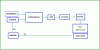
Maybe next we can take a look at a control system block diagram to see what this is all about.
 

Attachments

  • ControlScheme2.gif
    ControlScheme2.gif
    10.5 KB · Views: 360
Maintain (adjustable) 155 - 200 F set point with lo-speed. +- 0.1 degree F tolerance. Fan soft starts 1 degree cooler than set point.
Turn on hi-speed when temperature goes 2 degrees F above set point. Turn off hi-speed when temperature falls below hi-speed turn-on temperature.
Turn off lo-speed when temperature falls 1 degree F below set point.
:confused:I don't see how those targets can be met. Maintaining temperature within 0.1 degree, taking into account changes in wind speed and engine rpm and the thermal inertia of the whole coolant system, is IMO unrealistic. Even if it were possible then the temperature would not go 2 degrees above set point or 1 degree below set point, so the turn on/off would never occur.
 
I appreciate all your thoughtful insights, KISS. Here are some photographs.

"MOTOR1" shows the thermostat housing and temperature sending unit mounted to the top/font of the engine. NOT measuring radiator coolant temperature.

MOTOR1.JPG


"MOTOR2" shows the 3 wires that are connected to the motor.

MOTOR2.JPG


If you look at "MOTOR3" through" MOTOR5" carefully, you can see how the armature winding rotates with the armature shaft. I assume this means the motor has brushes.

MOTOR3.JPG MOTOR4.JPG MOTOR5.JPG
 
Last edited:
KISS, There is storage in the system - if I'm understanding your use of the word "storage" correctly. It's in the form of coolant capacity of the radiator - approximately 6 quarts - and the engine block/cylinder head- about another 6 quarts. Coolant in the bottom of the radiator is coolest. Coolant at or near the sending unit is hottest. It's impossible for 3 gallons of coolant to immediately cool and reheat as quickly as you seem to indicate it will.

As the engine idles, the coolant temperature will steadily rise until the circuit reaches the setpoint and turns the fan motor on.

The temperature of the coolant in the engineblock/cylinder head will not immediately begin to fall.

The temperature of the coolant in the engine block/cylinder head will continue to rise for a period of time even after the fan turns on.

The temperature of the coolant in the radiator will begin to fall below the setpoint of the circuit within moments after the fan turns on.

The coolant leaving the radiator will never effect the sending unit for the period of time it takes for it to pumped back up to the top of the engine block/cylinder head.

Once the fan turns on, there will be a delay - especially at idle RPM - until the sending unit begins to see the coolant temperature fall back down to the setpoint.

Certainly not the instant on-off chattering relay you suggest. I still do not see why one setpoint won't work.
 
One setpoint can work if it's PI (proportional Integral) control which is what Mr Al suggests in his diagram. We all agree that 0.1 degrees is unrealistic for control.

PI and bang-bang control are two different animals altogether.

In bang-bang control, suppose that the setpoint is 160 F. Below 160 is on and above 160 is off. In this case the motor is trying to constantly start and stop and in some cases it just tries and may not even get to start. The result is worn brushes.

In bang-bang with hysteresis, at least the motor gets to start and stop for maybe 10 degrees or whatever, but it's still not as good as PI control.

The Integral term of PI control attempts to make the setpoint and the measured value agree. Think lie a cake mixer. As the load increases on a stupid cake mixer, the speed decreases, so you keep moving the dial. Think of the dial position as the proportion of full voltage. Without feedback, that proportion keeps changing depending on load.

So as the car moves faster, and the same proportion (0-100%) is used, a different temperature results.
e.g. %out = (Setpoint-measured value)*kp)*100 The value of kp, the proportionality constant will change based on car speed, ambient temp etc. The Integral term (not shown), attempts to add or subtract from %out depending on the error.

The integral term can be expressed in units of "repeats/minute", so a fraction of the error is added/subtracted every so often, thus changing the amount of cooling.

Just the difference of the setpoint and the measured value is not enough information to control the motor speed which in turn controls the temperature.

The proportionality constant is normally shown in the denominator in control theory.
 
KISS, There is storage in the system - if I'm understanding your use of the word "storage" correctly. It's in the form of coolant capacity of the radiator - approximately 6 quarts - and the engine block/cylinder head- about another 6 quarts. Coolant in the bottom of the radiator is coolest. Coolant at or near the sending unit is hottest. It's impossible for 3 gallons of coolant to immediately cool and reheat as quickly as you seem to indicate it will.

As the engine idles, the coolant temperature will steadily rise until the circuit reaches the setpoint and turns the fan motor on.

The temperature of the coolant in the engineblock/cylinder head will not immediately begin to fall.

The temperature of the coolant in the engine block/cylinder head will continue to rise for a period of time even after the fan turns on.

The temperature of the coolant in the radiator will begin to fall below the setpoint of the circuit within moments after the fan turns on.

The coolant leaving the radiator will never effect the sending unit for the period of time it takes for it to pumped back up to the top of the engine block/cylinder head.

Once the fan turns on, there will be a delay - especially at idle RPM - until the sending unit begins to see the coolant temperature fall back down to the setpoint.

Certainly not the instant on-off chattering relay you suggest. I still do not see why one setpoint won't work.


Hi again,

There are some digitally based voltage regulators that work with only one set point, if that's what you want to try first. The 'delay' you talk about is caused by what is considered system storage which is a electrically equivalent to capacitance and possibly some inductance, so it forms a sort of switching regulator. It's a somewhat crude technique however compared to the other types, but it does work.
It's almost like charging a capacitor through an inductor with some resistance, and when the voltage gets to a certain point the driver is turned off. The cap voltage keeps rising though for a short time because the inductor still has excess energy, and when it starts to fall depends on the natural frequency of the circuit. Once it does start to fall, it then reaches the set point again and turns the driver back on. There's usually a small amount of hysteresis just to keep the noise from causing a high speed oscillation during the switchover times.

We could start with a system like that and you could implement it and do some testing to see how well it works. That would be one of the simplest circuits and would provide at least a starting point.

The other question that comes into mind involves what actually happens in a car with the right parts already installed such as the temperature sensor. My car has the temperature sensor on the radiator, but also has a normal thermostat mounted on the motor in the usual place. So the sensor on the radiator only controls the radiator temperature, while the normal motor thermostat controls the temperature of the motor. We might ask if we really want to mess with this already working system. The thermostat on the motor already takes care of the engine temperature. The electrical thermostat on the radiator is probably just there to keep the motor run time shorter for better longevity and maybe also to allow the car to heat up faster in the winter time. So you might want to think about how much you really want to change all that anyway, and maybe try to find some after market systems that are already in existence and see what they are doing.

So keep in mind that the mechanical thermostat on the motor is already doing what is needed, so maybe you are over thinking this problem.
 
KISS, the aftermarket electric radiator fan never turns on while the car is moving. It prevents overheating, when the car is stopped. The stock, belt driven fan (removed) did not do as good a job. The thermostat in the engine maintains engine temperature perfectly except when there is no airflow i.e. car stopped.

MrAl, What I'm trying to do is keep the aftermarket fan from running too long. It has a large a range of temperature between on and off. Once it turns on, it rarely shuts off until the car gets moving again. It has a mechanical sensor mounted in the radiator. Yes modern cars and most aftermarket radiator fans/kits have radiator mounted fan sensors. Very few aftermarket fan sensors are made to mount anywhere BUT the radiator. There are a few that go into the block, the head or a hose.

Thank you both for sharing your automotive cooling system knowledge with me.
 
OK, I know when I'm licked. OpAmps are apparently the only choice with regards to efficiency. I'm really trying to not ignore anyone's suggestions. It's just that I need to know what I'm doing before I can try to do what anyone is telling me to do. Here is my latest iteration :
2 X LM 318 buffers drivers.png
2 X LM 318 buffers drivers-graph full scale.png
2 X LM 318 buffers drivers-graph.png
 
Hi,

What else do you need to know?

You dont seem to want to go with any suggestions we make anyway, you just go on your merry way back to something that probably wont work. I hate to sound negative here, but you dont seem to like to take advice very well.

For example, who said anything about using an LM318 op amp, where did that idea come from? I suggested an LM358 for a good reason, and i thought i made it clear. Some of the other op amps (LM318 included) do not work well in control applications unless their supply voltages are around plus and minus 15 volts. Also the bandwidth of something like 15MHz is much higher than needed as this will be a very slow control system on the order of 1 second time constant or even longer. But the worst part is the input and output requirements, which make using it that much more difficult. The LM358 works all the way from ground up to about Vcc-1.5 volts, which isnt bad at all. And the output can reach down near zero too and up to about Vcc-1.5 volts as well. The LM318 can not get even close to that with about a 4v margin between supply rails, both on inputs and output. So with a 12v power supply the inputs and output of the LM358 can work from 0 to 10.5 volts, while the LM318 can only work from 4 volts up to 8 volts, but inputs and output.

I am assuming you need op amps, but if a comparator will do then the LM339 should work well.

Your schematic is getting there though. I must say at least now you agree that op amps are a necessity. After testing if you find that you can put up with a little more variation we could always go to simple custom op amps made with transistors. That probably will never be necessary though.

Oh yeah one more thing:
A mechanical bypass switch. During testing it might not go as well as expected. If you are on the road you wont want to have to pull over to wait for the engine to cool off naturally if the control system fails. A simple heavy duty mechanical switch will get you going again even if you have to drive far to get home.

A little attention to detail in an automotive app means we also have to be aware that the power line will be noisy, so some filtering is a good idea and maybe even a zener to protect against over voltage transients.

Also, what are the 1M resistors doing?
 
Last edited:
The OP said earler that he didn't have a model for the 339. He was also "warned" that the circuit may not survive in the automotive environment.

If anythng. the OP has to look at us as mentors. I tend to stimulate the thought process.
 
KISS, You got that right. I need mentoring ... but I try to remain humble ... humble enough to remain able to learn ..

MrAl, I'm sorry but please try to be understanding with me. I can see how it would be irritating to get ignored after I came here looking for help. Fact is, I used my poor memory and grabbed the wrong OpAmps. I honestly did not realize before this, how vastly different each OpAmp is and I made a hasty choice, without re-reading your posts. To my surprise, a 358 is in my simulation software's library so I swapped out the 318s as per your suggestion. I also put in a couple of variable resistors to adjust the turn-on voltage/temperature setpoints for each OpAmp.

I'm still not quite understanding why a comparator would be the best choice, since I am going to be using one setpoint for each motor speed. If I could have figured out how to do this part of the circuit using two tansistors instead of OpAmps, I would have. I'm not trying to be so ignorant about this but the simple truth is ...

I am also still considering to use just the hi-speed capability to initially test the basic circuit. If I do that, I may try to allow for a different "turn-off" temperature/setpoint from the "turn-on" setpoint. If I understand properly, this is when it would be best to use a window comparator.

The 1M resistors are my feeble attempt at further reducing any effect this circuit will have on the temperature gauge readings. I'm also attempting to design a circuit that uses the least amount of current as possible and still do the job reliably. Is it totally unnecessary to use any resistor on the OpAmp +(tive) inputs ?

I'm defintiely there already with at least one of your suggestions, MrAl. I installed an override switch to operate the aftermarket fan motor relay manually, 10 years ago. I also included a dashboard mounted indicator light that turns on, whenever the fan motor is running, whether manually or automatically.

My next step in designing this circuit, providing there are not any other glaring errors, is to put in the power resistors that will either connect directly to the motor windings or to relays. I will definitely add components as needed, to help prevent brown-out problems as well as protection from voltage spikes and filters electrical noise from the circuit once I have a "mule" that I can physically test and it works.

I can't thank all of you enough for the help you've given me already. I'm thinking I would do well to post on the simulation software category to see if I can get more library models to use. Anything to avoid pissing off the locals hey ?
 
more library models to use
.... are freely available via the Yahoo LTspice User Group.
 
with 358s and variable resistors. 1M resistors removed from +(tive) inputs :
2 X LM 358 buffers drivers with pots.png
 
KISS, "Optimized for saturated operation" says it all. ty

Alec T, I look at the Yahoo group, installed LTspice and whoa is me ! It seems the models are not compatible with the software I've been using. It seems I made the wrong choice of freebie simulation software. Now I need to learn how to use LTtspice.

One thing I did learn thanks to Alec T's link is that the LM339 "comparator - not an OpAmp" is in my software's library. It's under "Comparators", of all things. I was looking for it under operational amplifiers. Feeling a little stupid not being able to find it before this. Oh well. Not an unfamilair feeling to me- freshly folded brain tissue.

Guess I need to swap out the 358s with 339s ... with your permission of course, MrAl.
 
Hello again tyrebyter,

I am not trying to act lyke a dytator here, just trying to hylp <chuckle>

It appears that you do want to ask questions and that's always good. And because i have guided so many people over the years both on the web and in real life both on and off the job, i guess i am just too used to people following my lead on these kinds of projects so when someone doesnt it seems strange to me at first. But i do understand your situation better now, and i think you are trying to take all this in at once and that makes it difficult i know. So with that little humor above i offer i hope it will help lighten things up a little now. Not sure if the smilyes are working right either yet with the new site software or i would have used some.

So ok, now you've discovered that there are some serious differences between op amps, and there is some difference between op amps and comparators, and that's very good. For this app the main difference between the LM358 and the LM339 is that the 339 output can reach all the way up to +Vcc (so like +12v with the car engine not running) whereas the 358 can only reach up to about Vcc-1.5v (so like 10.5v with the car engine off). Of course this might not matter depending on what we have to drive with it. For example, we may get away with driving a MOSFET at slow speed, but trying to drive a PNP transistor with emitter connected to +Vcc gets a little challenging because we might not be able to turn it off properly with only 10.5 volts (and base resistor).

Since KISS mentioned that you might not be able to get the LM339 in a wider temperature package (like mil spec) and you can get the LM358 in the right package, we can easily equalize the two by using a resistor and NPN transistor at the output of the LM358 which turns the output into an open collector output which is the same as the LM339. We'll wait on that and maybe we wont need that.

As to any other differences, i know that the LM358 works ok as a comparator as long as the output is ok for the application because i have used it as such in a lower frequency (60Hz) application. Since this project will be very low frequency (1Hz or maybe even lower) the speed should not be a problem.
Driving a MOSFET directly however may or may not be a problem, depending on how much power each switch cycle adds to the MOSFET package. It should not be too much though i dont think because it will be switching so slow (1 second or longer intervals with proper design).
The slew rate of the LM358 is about 0.5v/us, which means the output can go from 0v to 10v in 5us, which should be more than fast enough.

So if you would like to use LM358's or LM339's we should be able to adapt either to this project, as long as you can get the packages in the right temperature category for automotive use (mil spec parts would be great here).
I also dont know what your outside temperature extremes are where you live.

As i was saying in a previous post, a window comparator is made from two comparators as you are doing i think. Normally this is used to switch an output on or off when the signal level is *between* two set points. But for a fan controller it has to be a little different because we want slightly different operation. When the fan turns on it has to latch on, until the other set point is reached, then turn the latch off. That's because the output changes state at times we dont want to switch anything on or off so we have to have a latching mechanism of some kind. This can be a simple latch or we can make up an analog latch with another comparator section. That's up to you. If you look at one of my previous posts i had drawn a schematic of the basic setup. The only difference really is that your circuit would run the two outputs to the latch Set and Reset inputs, that's all.

LATER
I just checked and it looks like both parts are made in mil spec packages, the LM139 and the LM158. One might be easier to obtain than the other however.
 
Last edited:
In any event there are a bunch of OP amp/Comparator/reference IC's that might be able to be substituted (surface mount probably). Wikipedia says higher frequencies like 40 kHz needs to used for a "Pancake motor" and this may qualify as such.
 
Hi,

What has to be 40kHz?
 
Difficult for me to get models from the Yahoo LTspice group. As an example I grabbed the first NPN in my library. It's being driven by X3, the hi-temperature/hi-speed control (bottom comparator). If I add one more stage after this, add a transistor which would be powered from 12 V and can adequately deliver enough current to energize a relay at Q1-out, is this how the circuit would look ?

2 X LM339  one drives a  BC107.png
 
MrAl, Once I have something that works in simulation, I will begin looking for physical components. I understand there will likely be some give and take as far as getting the best I can, according to what is available etc.

To answer your question regarding temperature :

Typical ambient/underhood temperature is in the range from (minus) 40F with windchill to (plus) 250F during heat soak - after the engine is shut off.
Where I live it can get over 100F for a day or two, some summers.

Now I have to read up on what a latch is in your circuit.

I believe KISS is mentioning 40khz as a good pulse frequency for an electric motor PWM controller. Under 20khz (upper limit of human hearing) apparently causes the motor to make an annoying sound.
 
Status
Not open for further replies.

New Articles From Microcontroller Tips

Back
Top