Continue to Site

Welcome to our site!

Electro Tech is an online community (with over 170,000 members) who enjoy talking about and building electronic circuits, projects and gadgets. To participate you need to register. Registration is free. Click here to register now.

  • Welcome to our site! Electro Tech is an online community (with over 170,000 members) who enjoy talking about and building electronic circuits, projects and gadgets. To participate you need to register. Registration is free. Click here to register now.

Arduino Trigger

Status
Not open for further replies.

DBIRKY

New Member
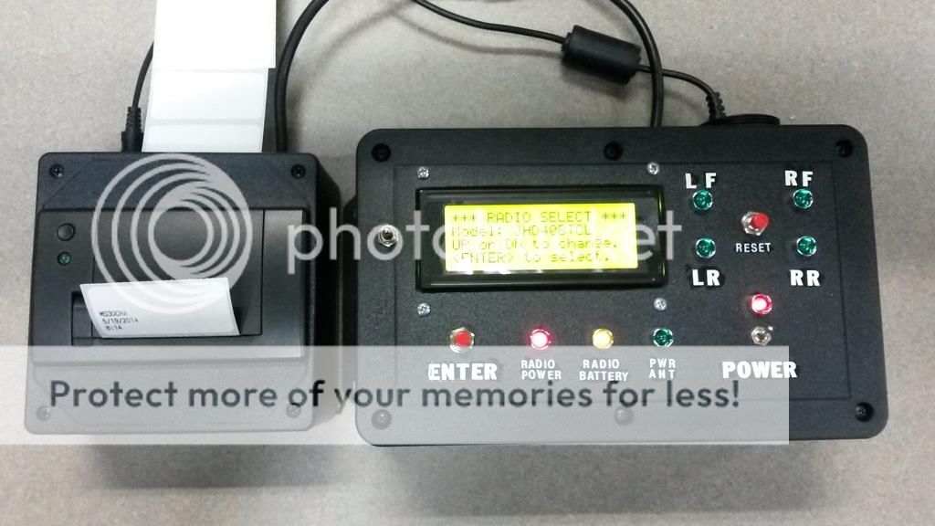
I am writing a program that will test radio harnesses custom pinned for a customer. I have messed with some simple VU meter program code and can get 1 line to work fine. My issue is when I connect all 4 (left front, right front, left rear, right rear) that I get all 4 lines triggering even when there is no signal going to them. I don't need to know what the levels are... basically is there signal or no. I'd be game for each speaker lead to trigger a transistor allowing 5V to be read by digital pins. This needs to be simple and as few discrete components as possible. Triggering the transistor is looking better than direct connect to an analog input. The speaker values are in mV.
Any help would be appreciated!
Thanks!
Doug
 
Need more information.
The speaker values are in mV.......is there signal or no
1mV? 10mV? 100mV? 837.98mV?
radio harnesses custom pinned for a customer
4 wires, Printed Circuit Board?
I don't need to know what the levels are...
I do need to know what the signals are. 10mV=0, 11mV=5V You need to define where no_signal and yes_signal is.
 
Well, the project is finished. I ended up using a quad-opamp and made a designed a PC board for the input from the speakers. Its a shield that will work with the UNO or MEGA. Basically it reads when a speaker output is live or not. If it is the output to the Arduino goes high. If not, it stays low. The Arduino then lights LEDS to indicate which channel the radio is faded to. Using a 4x20 LCD it prompts the operator to set balance/fade/and volume levels as well as cycle through different radio model numbers. Once the test is complete it prints a label that has the time, date, and model number on it. These QC labels are then affixed to the radio harness. It works well.


20140519_094100_zps94a332ca.jpg
 
Last edited:
Status
Not open for further replies.

Latest threads

New Articles From Microcontroller Tips

Back
Top