Continue to Site

Welcome to our site!

Electro Tech is an online community (with over 170,000 members) who enjoy talking about and building electronic circuits, projects and gadgets. To participate you need to register. Registration is free. Click here to register now.

  • Welcome to our site! Electro Tech is an online community (with over 170,000 members) who enjoy talking about and building electronic circuits, projects and gadgets. To participate you need to register. Registration is free. Click here to register now.

Aqualuma LED´s

Status
Not open for further replies.

2PAC Mafia

Member
Hello people,

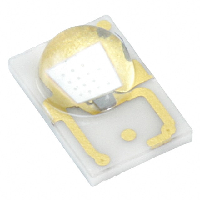
I have this light from a boat, it is double light blue or white. It´s connected to a 24V power source, then it has two DC/DC Recom 24-0.5 converters. The output is connected to a board with 3 white LED and 2 blue LED. The blue LED were in short so the DC/DC was protecting itself.

OK, I´m looking for these type of blue LED. Dimmensions are 4,6mm x 3,1mm. I don´t have information. I only measured the current through a white LED when I connected 3,3V on it and consumption is around 80mA for each.

Some pictures:

http://www.restoretronic.com/descargas/Aqualuma/1.jpg
http://www.restoretronic.com/descargas/Aqualuma/2.jpg
http://www.restoretronic.com/descargas/Aqualuma/3.jpg
http://www.restoretronic.com/descargas/Aqualuma/4.jpg
http://www.restoretronic.com/descargas/Aqualuma/5.jpg
http://www.restoretronic.com/descargas/Aqualuma/6.jpg
http://www.restoretronic.com/descargas/Aqualuma/7.jpg
 
A metric 4613 size is probably obsolete or non-existent now.

If you can solder the Cathode to the thermal pad OK, any size bigger will do as they have the same voltage.

The problem is the designer neglected the effects of Thermal Runaway when the ESR of the three (3) Blue in series does not match the ESR of the three (3) White in series.

Power at 80mA*3.2V = 1/4W and ESR will be approx 4 Ohms =+/-50% or 12 Ohms with 3 in series.

There is a trick to compute tolerance of ESR vs thermal resistance which causes Shockley effect or NTC voltage but is beyond scope here.

Replace all B,W LEDs with 5050 size chips from same vendor and specs. https://www.digikey.ca/product-detail/en/XZCB25X92S-4/1497-1089-1-ND/4745492

Consider adding 0.3R~1R in series with each color in parallel. I call this the Shockley compensation equalizer to prevent thermal runaway.

Then add water clear epoxy coating to prevent moisture damage.

The result should be a much more reliable and brighter product as this design had 2 faults.

You can use AWG 30 or 40 wire to solder Anode to tracks. Solder time 3s max.


I might even scrap the FR4 board and retrofit MCPCB with Blue and White emitters.

This 10 yr old design is lacking some reliability.
 
Last edited:
Raises a question in my mind- Epoxy ,clear coat . At what temperature do these run and at what point does the epoxy coating char and burn? I don't think I will be doing that until they have heat resistant clear epoxy. I think I would stick to coating the connections and other parts only.

The trouble with fools is that they do not realise their foolishness.
These forum sitters you have here are a pain . They don't try to help really . What they do is jump in and confuse the thread.
You don't know anything about a situation unless you have experienced it specifically yourself ! Period
I suggest you stop wasting peoples time who come here for an answer.
Leave the answer to someone who does know.

In my case the answer was simple but I found it on a more sensible forum -not this circus
 
Last edited:
Raises a question in my mind- Epoxy ,clear coat . At what temperature do these run and at what point does the epoxy coating char and burn? I don't think I will be doing that until they have heat resistant clear epoxy. I think I would stick to coating the connections and other parts only.

All 5mm LEDs use water clear epoxy. It has a lower melting or glass transition temp than black epoxy, but obviously, higher than max. Tj. However, hand soldering can ooze epoxy seals around leaded parts when exceeding 5s , which compromises the moisture seal..
 
The main thing is that all 3 LED didn't blow at once due to bad parts. It was a marginal design with higher Tj on smaller blue LED chips or higher Pdiss from higher ESR, Vf.

The other consideration is matching the required Luminance or Iv of the designed parts before with replacement parts. There is a wide range and optimal matching can be obtained with reducing Iv by adding 1 Ohm increments in Blue .

The use of a tiny SMD LEDs on FR4 was a marginally poor choice with these power levels.

I may have misread the photo as 2P3S array of LEDs or 1P6S or switched 3S white or 3S Blue.

Are Blue and White on exclusively or at same time? Is this 500mA CC for either string? Or two independent 500mA CC sources.

There are 3+3 LEDs per board, right? Not 3+2.
 
Last edited:
I agree on Luxeon Rebel. questions remaining...which dominant wavelength, Luminous Intensity, Thermal Resistance?

I would opt for Royal blue, Max Intensity, and lowest Thermal Resistance,, the CC source can be adjusted to suit downwards.

LXML-PR02

Iv bin codes
D 18.1 23.5 ( no)
...

M 90 100 ( maybe)
N 100 110
X 110 120 ( yes)
P 120 130 "
Y 130 140 "

Reflow skills come to bear with short dwell times and good prep & thermal pad bonding that affects thermal Rca significantly.

There are many other bin choices for Vf, Pmax and obviously lower Vf means cooler LED and longer life.
 
Last edited:
Hi,

the epoxy is out because I had to desolder them with heat gun. Don´t worry about that.

There are 3 LED white and three LED blue in series with two power sources coming from two different DC/DC 500mA. I guess they work independently, one or the other.

I only find 20mA LED and my doubt is about light bright (IV, MCD) as I see white LED very bright but I don´t know the way to find the proper compatible LED. I would say MCD is directly associated to V and mA, isn´t it?

I used these ones:KPTD-3216QBC-D
but all burnt and damaged the DC/DC...

I indicated which were the best match LXML-PR02 series and how to match it with DC-DC adj These operate at 500mA not 20.. but only if soldered properly to thermal pads or MCPCB.
Since the FR4 is a 2x sided board with fairly large thermal pads, solder requires a hot plate and hot air reflow with paste over a very clean flat surface.

next best is ok too LXML-PR01 series slightly hotter.

these radiate >10x the ones you picked.
LXML-PR01-0500.JPG


Order here before 8pm GST-6 and they ship same day
https://www.digikey.com/product-detail/en/LXML-PR01-0500/1416-1038-1-ND/3961143

assuming it is Royal Blue. and not Std Blue.
 
Last edited:
Status
Not open for further replies.

Latest threads

New Articles From Microcontroller Tips

Back
Top