Continue to Site

Welcome to our site!

Electro Tech is an online community (with over 170,000 members) who enjoy talking about and building electronic circuits, projects and gadgets. To participate you need to register. Registration is free. Click here to register now.

  • Welcome to our site! Electro Tech is an online community (with over 170,000 members) who enjoy talking about and building electronic circuits, projects and gadgets. To participate you need to register. Registration is free. Click here to register now.

Anyone near Rotherham who could test my Scope?

Status
Not open for further replies.

bigal_scorpio

Active Member
Hi to all,

Thanks for all the info past, present and future guys. You have got me through some difficult problems!

After following a link from kchriste about Oscilloscopes I am beginning to think mine may be faulty. Its an old one that I acquired and never had instructions or specs for.

To be honest I cant even follow basic "How To" guides as my scope and the tutors never seem to have the same controls or parts!

E.G. in one guide it mentions the probe test that gives a square wave output, I have a test probe point but I cannot get a square wave from it, just a constant 4v trace!

Also I have never managed to get anything from the "A probe" and can even only get a test signal on "B" but I do get wild traces when touching the probes with fingers.

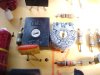
What I need is someone with scope expertise to check mine and maybe just get me going with what means what with my seemingly unusual scope (Scopex 140-10V). I would be quite happy to travel a reasonable distance if anyone is willing to help and show me the ropes or condemn my scope!

I live in Rotherham, close to the Meadowhall shopping center and M1.

If anyone can help please let me know. I am sure Eric Gibbs would help me as he has done with advice many times in the past but sadly he lives hundreds of miles away from me, maybe I should consider flitting closer hehehe, but seriously any help will be greatly appreciated.

Thanks for reading my plea................Al
 
Scope Service Manual

Here'e my scope service manual, or for anyone with a Scopex 14d-10(v) :)

Al
 

Attachments

  • scopex_14d10_technical_information.pdf
    1.9 MB · Views: 511
hi Al,
Have you managed to debug the ESR using the scope.:rolleyes:

Morning Eric,

Sadly when I went to Nigel's, I discovered that the "A" channel on my scope doesn't work. I kind of expected this as I could never measure a sine or aanything really on a so I had been using "B".

What I didn't know is that only the "A" channel will display waves as it has the trigger! And seeing as it won't work on "A" I'm stuck!

Nigel said that its usually the FET that has been blown by someone measuring too large a voltage, and indeed the service manual shows what I believe is a fet in each channel, but the schematic is strange to me, some parts of it seem to comprise of many small circles that are obviously meant to tell me something, but don't, have a look.

If you see anything you think may be the cause let me know, I didn't want to go exploring in the scope and perhaps change a working component and introduce more possible problems.

PS I also noticed what looks like white mould on ALL the presets in the scope, but isn't present on anything else. Is this normal for the age of it or some other reason?

I will get the wife to take some good close-ups inside the scope and post them here, see if anyone has seen the white stuff before.

Regards...........Al
 

Attachments

  • MVC-397F.JPG
    MVC-397F.JPG
    57.8 KB · Views: 301
  • MVC-398F.JPG
    MVC-398F.JPG
    54.4 KB · Views: 282
  • MVC-399F.JPG
    MVC-399F.JPG
    63.7 KB · Views: 288
  • MVC-400F.JPG
    MVC-400F.JPG
    52.3 KB · Views: 240
  • MVC-401F.JPG
    MVC-401F.JPG
    50.2 KB · Views: 238
  • MVC-402F.JPG
    MVC-402F.JPG
    69.6 KB · Views: 272
I think that white junk is oxidation. Maybe you need to replace the pots. Of course your calibration would go out the window. Maybe a good cleaner spray to remove the crud.
So, cool, you met Nigel...
 
I have a few pots of that style, they have sat in the drawer for 25? years, and guess what - they have a white film on them!
Not quite as spectacular a growth as those in the scope, but the same sort of thing.

At a quick guess, I think the pots will be OK, if the white stuff worries you, clean it off with a soft brush.

The "circles" you refer to are trying to represent the poles on the switches, the vertical sensitivity and the timebase.
I also think I see a couple of errors in the circuit as drawn, maybe a couple of lines missing between some of the groups of circles on the y sensitivity switches.

The little boxes with text such as ÷5 and ÷100 contain the circuits shown below in the chain dotted boxes.

JimB
 
Last edited:
I think that white junk is oxidation. Maybe you need to replace the pots. Of course your calibration would go out the window. Maybe a good cleaner spray to remove the crud.
So, cool, you met Nigel...

Even cooler - I met Al :p

From the diagram I would suspect TR152, the input FET.

The fault was that the A beam was off the screen, and you couldn't get any sync even if you tried both inputs on the same signal.

As it's a dual beam scope, you might try swapping the FET over with the working channel, take static precautions though as it's an FET. See if the fault swaps beams.

At least he has a diagram now, even if it is a bit poorly scanned.
 
hi Nigel,

Did Al bring his WIP, ESR project for you to check out.?
 
Hi Al,

Measure the voltage at the junctions of R148/150 and R151/3K3
and also R149/150 and R152/3K3, vertical position centered,
vertical sensitivity at minimum.

Next measure the voltage at the junction of R149/150 and
R152/3K3, Vertical position fully clockwise.

Again measure at the same junction with the vertical position
fully counter clockwise.

on1aag.
 
hi Nigel,

Did Al bring his WIP, ESR project for you to check out.?

Yes, it oscillated, but only intermittently, I think his level setting preset, which didn't fit the board correctly, was faulty? - however, while he was there I dug deep (very deep), and managed to find the parts for the one I started building years back. This had a fully completed board, using the exact same components as the one I built for work - so I gave him all the lot, case and everything to go and play with :)
 
Yes, it oscillated, but only intermittently, I think his level setting preset, which didn't fit the board correctly, was faulty? - however, while he was there I dug deep (very deep), and managed to find the parts for the one I started building years back. This had a fully completed board, using the exact same components as the one I built for work - so I gave him all the lot, case and everything to go and play with :)

Thanks a lot, I was going to offer to take a look see, if you hadn't had the time.
 
Hi Eric, Nigel, on1aag and all,

Just openened the scope and looked for the TR152 as Nigel suggested. It is a CA3046 General purpose NPN 5 transistor array, B channel also has one TR252.

I swapped them round and still had no trace from A.

They don't seem to be FETs from the datasheet so I'm wondering if there is something else in another location I should check?

As to the checking voltages suggestion from on1aag, could you give me a bit more info IE what voltages I should be looking for?

I bet I bought another pup with the scope, people must see me coming. :(

Al
 
DOH!

Can't get anything on the scope now!

The only way I can get a trace on either input is to hold down "Locate"!

What have I done? :(

Al
 
Hi Eric, Nigel, on1aag and all,

Just openened the scope and looked for the TR152 as Nigel suggested. It is a CA3046 General purpose NPN 5 transistor array, B channel also has one TR252.

I swapped them round and still had no trace from A.

They don't seem to be FETs from the datasheet so I'm wondering if there is something else in another location I should check?

As to the checking voltages suggestion from on1aag, could you give me a bit more info IE what voltages I should be looking for?

I bet I bought another pup with the scope, people must see me coming. :(

The transistor I was refering to was an FET E421 (if I remember correctly), the diagram was a bit faint, but it looked like it said TR152?.


If neither traces work now, then swap whatever you did back again.
 
If neither traces work now, then swap whatever you did back again.[/QUOTE]

I have done mate, just seem to be having a lot of luck lately - sadly all bad! :(

Al
 
Were the CA3046s in sockets or did you have to desolder them? If in a socket make sure they are seated properly with no bent pins, etc. If socketed, you could remove the B channel one and do a quick diode check on the transistor junctions.
The way I would have tackled this, with channel B working, is switch both channels to DC coupling, 2 volts per division, and set all A&B controls identical. Then I would connect both A&B inputs to a 9V battery. Then I would have compared the DC voltages on both A&B channels until I found the point where they differed by more than 10%. BTW, the input FETs are located before the LM733s:
 

Attachments

  • FETs.GIF
    FETs.GIF
    45.4 KB · Views: 283
Last edited:
Were the CA3046s in sockets or did you have to desolder them? If in a socket make sure they are seated properly with no bent pins, etc. If socketed, you could remove the B channel one and do a quick diode check on the transistor junctions.
The way I would have tackled this, with channel B working, is switch both channels to DC coupling, 2 volts per division, and set all A&B controls identical. Then I would connect both A&B inputs to a 9V battery. Then I would have compared the DC voltages on both A&B channels until I found the point where they differed by more than 10%. BTW, the input FETs are located before the LM733s:

Hi kchriste,

Sadly neither channel works at all now and yes they are socketed.

But you gave me an idea mate, I usually can't check ICs but as you said I could test the junctions and even better I could use my Peak DCA meter on them, just by testing them as single transistors!

Getting excited now so I'm going to test them now, wish me luck, I'll post the results.

Al
 
Update

Hi Guys,

Tested both CA3046, in one all 5 Transistors show OK, the other shows T5 not as NPN but as diode network, so thats one problem found.

Swapped again and still no traces showing at all, but found something else strange. There is a pair of large resistors (R181 & R182) below TR256 which are getting quite hot, beside them is an identical setup with the resistors (R184 & 186 I think - numbers on schematic are poor) below TR259, these are not getting anywhere near as warm.

Could this be a sign that TR259 and/or TR256 are faulty, what do they do?

Any thoughts guys?

II will have to order some CA3046s from rapid, so if anyone can see any other possible iffy components let me know.

Thanks to all..................Al
 
Last edited:
Hi Guys,

Tested both CA3046, in one all 5 Transistors show OK, the other shows T5 not as NPN but as diode network, so thats one problem found.

Swapped again and still no traces showing at all, but found something else strange. There is a pair of large resistors (R181 & R182) below TR256 which are getting quite hot, beside them is an identical setup with the resistors (R184 & 186 I think - numbers on schematic are poor) below TR259, these are not getting anywhere near as warm.

Could this be a sign that TR259 and/or TR256 are faulty, what do they do?

Any thoughts guys?

II will have to order some CA3046s from rapid, so if anyone can see any other possible iffy components let me know.

Thanks to all..................Al

Hi Al,
They appear to be Y amp push/pull drivers. If the traces are off the screen, its likely one pair is driving hard and the other is not, thats why there is a tempr difference.

I have been looking at the circuit diagram, if you need more 'input' let me know.:)

Can you still get a trace when you press the 'locate pb'.?
 
Last edited:
Status
Not open for further replies.

Latest threads

Back
Top