Electro Tech is an online community (with over 170,000 members) who enjoy talking about and building electronic circuits, projects and gadgets. To participate you need to register. Registration is free. Click here to register now.
Welcome to our site! Electro Tech is an online community (with over 170,000 members) who enjoy talking about and building electronic circuits, projects and gadgets. To participate you need to register. Registration is free. Click here to register now.
Check my PIC tutorials which provide examples for just such an occasion:
The load should ALWAYS be in the collector, not the emitter (a common rookie mistake) - and my tutorial shows both source and sink examples (sink is easiest, and only requires a single transistor).
The load should ALWAYS be in the collector, not the emitter (a common rookie mistake) - and my tutorial shows both source and sink examples (sink is easiest, and only requires a single transistor).
If used as an switch then I agree. But if the load is on the emitter, then the emitter will follow the base voltage minus 0.6V. We call this an emitter follower. There is a time and a place for such an BJT configuration. Typically in the analogue domain...
If a good small signal transistor has a current gain of 240 , hFE, then this ratio is acceptable, but R is not meant to be 1 Ohm here but a fixed value much greater than the rBE which is Ibe dependent, referring to the base emitter resistance.
A Reasonable load R may be 100 Ohms which may be scaled down or up depending on transistor rating.
The reason this Emitter Follower works better is than a collector load, is due to the high Vc voltage which makes the transistor lossy with large VI drop but also makes it Linear for high current gain.
using the collector for inverting output switched loads saturates the Vce and also makes it nonlinear and gain drops to 10% of max linear hFE gain or typically Vce(sat) is rated at Ic/Ib= 10 vs ... 240 in this good example. And as high as Ic/Ib=50 in super low Vsat transistors by Diodes Inc.
This configuration only gives a 5-0.7V output swing with lower input current, but higher losses on 24V supply. These are the tradeoffs.
I agree that Collector output is best for full swing loads, but in this case it is only 5V swing desird from a 24V supply, which is ~ 4.3/24% =18% efficient .
If a good small signal transistor has a current gain of 240 , hFE, then this ratio is acceptable, but R is not meant to be 1 Ohm here but a fixed value much greater than the rBE which is Ibe dependent, referring to the base emitter resistance.
A Reasonable load R may be 100 Ohms which may be scaled down or up depending on transistor rating.
The reason this Emitter Follower works better is than a collector load, is due to the high Vc voltage which makes the transistor lossy with large VI drop but also makes it Linear for high current gain.
using the collector for inverting output switched loads saturates the Vce and also makes it nonlinear and gain drops to 10% of max linear hFE gain or typically Vce(sat) is rated at Ic/Ib= 10 vs ... 240 in this good example. And as high as Ic/Ib=50 in super low Vsat transistors by Diodes Inc.
This configuration only gives a 5-0.7V output swing with lower input current, but higher losses on 24V supply. These are the tradeoffs.
Dear Nigel, which part of my explanation did you not understand? and to answer your question. yes.
load should ALWAYS be in the collector.. will never work with input R 240x emitter R unless it is either a Darlington or a quasi Darlington NPN-PNP pair, then you have no need for 24V supply given for a 5V load unless you really wanted a 24V load with a 24V switch.
As I indicated to use the Collector output as a switch, Vce(sat) is always rated at Ic/Ib=10 unless super low saturated Transistor then = 20 to 50 current gain.
Thus if you want to switch 5V from 5V the Rb/Re ratio must be 10 and not 240 for a single standard switching transistor. Then the collector emitter switch reistance Rce times Ic collector current causes the rise in Vce.
To answer the OP's question, it didn't work for 1 of 2 reasons
1) you used Re= < 100 Ohms which demands a lot of current and current gain will drop under these conditions for an undersized transistor.
2) the transistor selected does not have hfe>=240 which is required for this to work.
THis might be a nominal gain for some small signal transistors but worst case can be as low as 20% of nominal. Better parts are binned in +/-25~ 50% ranges.
Still offering nothing except confusion for the OP, you appear to be posting to try and 'make yourself look clever' and failing badly?.
The original circuit didn't work because he used an emitter follower, the fact that his component values were incorrect makes no difference at all, an emitter follower isn't going to work in this instance (fairly obviously).
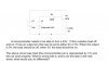
For this to switch 24V with 1Ω means the load is <24 Amps or 24*24= 576 Watts, if you arbitrarily choose 1% losses this is <6Watts.
To make this work with a 240 Ω Rb from 5V will only supply (5-0.7)/240 = ~20mA source current. thus the current gain required is 24/0.02=1,200
Note for low power dissipation of say 6W the switch resistance must be 6W/ 24^2=R<=10.3mΩ
Cost tradeoffs exist for very low Rce then RdsOn in a FET and then a Relay rated at 25~30A and heatsink cost for high loss
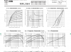
This excellent darlington needs a big heatsink but it satisfies the current gain but Vce@24A is 2V or 48W ( like a small CPU needs a big heatsink $
the load is reduced also by drop from 24 to 22V. or 22A or 484 W but this has 10% losses.
Still offering nothing except confusion for the OP, you appear to be posting to try and 'make yourself look clever' and failing badly?.
The original circuit didn't work because he used an emitter follower, the fact that his component values were incorrect makes no difference at all, an emitter follower isn't going to work in this instance (fairly obviously).
I explained how his circuit would work. >100Ohm load
Why it works
Why open collector is better but worse for current gain.
The open collector wont work either.
Sid , there is no great low loss solution for 24A using BJT's without very careful selection of components in a complementary 3 stage common emitter approach.
Still offering nothing except confusion for the OP, you appear to be posting to try and 'make yourself look clever' and failing badly?.
The original circuit didn't work because he used an emitter follower, the fact that his component values were incorrect makes no difference at all, an emitter follower isn't going to work in this instance (fairly obviously).
Jokingly in social conversation I offered him a job in my shop. He replied that I could not afford him...
When I was in my 20's I had tickets on myself. Today I am approaching 40-years of age and no longer see myself as being any better / clever or smarter than anyone else. I will happily clean your toilet for minimum wage. I won't knock back a dollar
I work here and volunteer elsewhere for less than min. Wage and my accomplishments in my career would not have occurred unless I had the opportunities I had to work with the brightest engineers in Canada and usa. I thank all my mentors. I once flew on short notice to Scotland to fix a design issue in disk driver controller, data separator. They wanted to fly my family over and stay for 6mos. i fixed the problem in 2 days and spent the weekend walking around London before returning to wife and 3 kids when I was 28.
I work here and volunteer elsewhere for less than min. Wage and my accomplishments in my career would not have occurred unless I had the opportunities I had to work with the brightest engineers in Canada and usa. I thank all my mentors. I once flew on short notice to Scotland to fix a design issue in disk driver controller, data separator. They wanted to fly my family over and stay for 6mos. i fixed the problem in 2 days and spent the weekend walking around London before returning to wife and 3 kids when I was 28.
Self-confidence is an great entity for success, but you talk above people and put people down. It seems as if you have something to prove.
Perhaps I am mistaken and this is not your true character in real life. Profiling people on the Internet can lead to all sorts of false positive and negatives. I mean fact of the matter is that electronics / physics is THE hardest subject to learn. I'll be honest and say that I probably know half of it.
Go easy on people aye and try not to confuse them just to make yourself look smart or ... more knowledgeable.
But an moderator has already spoken these words and it is best not to argue otherwise they will be going out of their way to try and find / justify a reason to remove / ban you. And this is perfectly normal human nature...
Suggest that you address the moderators as "Sir" to avoid the perils...
This site uses cookies to help personalise content, tailor your experience and to keep you logged in if you register.
By continuing to use this site, you are consenting to our use of cookies.