Andy1845c
Active Member
I just got a 2 meter transciver a few weeks ago. Its a Kenwood TR-7400A I thought it would be fun to have some local contacts.
I hooked it up to my 20 meter inverted V dipole that I have on my roof, just too see if I could hear anything. I could hear the local 2 meter net come in pretty good sunday night. Even made a weak contact using the 20 meter antenna.
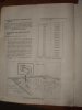
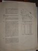
Well, I built a 2 meter J pole antenna. This one is the plan I used, but there seem to be about a hundred that all look very much alike.
https://www.n7qvc.com/copper.html
I finished it tonight, and I hooked it up inside, standing in a corner, and the results were pathetic. With the 20 meter dipole, I could get the output meter to read about a 6, with the 2 meter antenna, less then a 2! I tried moving the feedpoints, with no real change. I don't have a SWR meter for the 2 meter band, so I am just using the "output" meter and what I hear being recived to gauge my success (or lack of ) The manual says the meter should read around a 9 with a good match.
I'm hoping a fellow ham can answer a few questions so I can maybe understand this all better.
Can I even expect this antenna to work at all inside a house? I know outside is always better, but I thought it would work better inside then a completly wrong antenna outside.
If I have the 2 meter antenna and a 20 meter antenna both outside at about the same hight, should the 2 meter greatly out preform the 20 meter for receiving? Our is most of the differance going to be noticed when I transmit?
Why do some of the 2 meter J pole designs have the center of the coax on the long element and the braid on the short element, and some are the other way around? Does it matter? I have tried both ways.
I have some other questions too, but I'll wait and see if someone can help me first
I hooked it up to my 20 meter inverted V dipole that I have on my roof, just too see if I could hear anything. I could hear the local 2 meter net come in pretty good sunday night. Even made a weak contact using the 20 meter antenna.
Well, I built a 2 meter J pole antenna. This one is the plan I used, but there seem to be about a hundred that all look very much alike.
https://www.n7qvc.com/copper.html
I finished it tonight, and I hooked it up inside, standing in a corner, and the results were pathetic. With the 20 meter dipole, I could get the output meter to read about a 6, with the 2 meter antenna, less then a 2! I tried moving the feedpoints, with no real change. I don't have a SWR meter for the 2 meter band, so I am just using the "output" meter and what I hear being recived to gauge my success (or lack of
) The manual says the meter should read around a 9 with a good match. I'm hoping a fellow ham can answer a few questions so I can maybe understand this all better.
Can I even expect this antenna to work at all inside a house? I know outside is always better, but I thought it would work better inside then a completly wrong antenna outside.
If I have the 2 meter antenna and a 20 meter antenna both outside at about the same hight, should the 2 meter greatly out preform the 20 meter for receiving? Our is most of the differance going to be noticed when I transmit?
Why do some of the 2 meter J pole designs have the center of the coax on the long element and the braid on the short element, and some are the other way around? Does it matter? I have tried both ways.
I have some other questions too, but I'll wait and see if someone can help me first
Last edited: