Nepaliman
Member
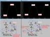
Did you mistakenly calculate with 1 M resistor? Diagram has 10 M resistor. I tried once myself but I am being fool.
Oh! If it has low current consumption then it might has very low level output, isn't it?
And, If I need high level audio (high gain), than can I use 10K Rc and 1 Meg Rb (approximately)?
(I thought it is related to input signal level of base, but I was wrong). Now I guessed why base of jFET has 44 Meg, because its collector audio level should be low because collector goes to 'Mic in'.
Last edited:
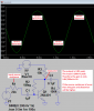
") . How great- current consumption is low but gain is high!
. How great- current consumption is low but gain is high!