Continue to Site

Welcome to our site!

Electro Tech is an online community (with over 170,000 members) who enjoy talking about and building electronic circuits, projects and gadgets. To participate you need to register. Registration is free. Click here to register now.

  • Welcome to our site! Electro Tech is an online community (with over 170,000 members) who enjoy talking about and building electronic circuits, projects and gadgets. To participate you need to register. Registration is free. Click here to register now.

another FM transmitter project

Status
Not open for further replies.
- I used 1st attenuator to attenuate the audio signal of cell phone's Audio (R Gnd) to feed the Mic in of PC. Hoping that audio level on earphone speaker will not be attenuated (?). Resistors' values are just guessed :)
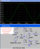
This attenuator is fine. Adjust the value of the 27k resistor for the correct level without any distortion.

- I am confused on 2nd attenuator because I have to attenuate ONLY the signal of 'Line out' of PC to feed the 'Mic in' of cell phone. But If I simply added an attenuator then the attenuator ALSO attenuates the signal of electret Mic of earphone and it is not good I think. Then how to add attenuator here?
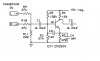
1) You need a coupling capacitor between the grounded attenuator and the biased mic.
2) The attenuator resistor values must be high enough so they do not attenuate the mic. Try 270k feeding 10k to ground or 470k feeding 47k to ground.
R3 is not needed.
 
You mean-

I should have to replace R3 with 330nF capacitor first.
Then R4=270k (series) and R5= 10k (parallel)
or R4=470k (series) and R5= 47k (parellel).

True? Thank you!


Then another-
How you calculated the attenuator (27k 27k and 1k) of mod 4? I have slow mind i think so cant use, tweak even ohm's law!

Once you calculated 280mV (line out) devided by 27k = 0.01mV.
I think this 0.01mV is suitable for input on Base of amp. But how you calculated the 1k parallel? What is that?
 
You mean-

I should have to replace R3 with 330nF capacitor first.
Then R4=270k (series) and R5= 10k (parallel)
or R4=470k (series) and R5= 47k (parellel).

True?
Yes, try it.

How you calculated the attenuator (27k 27k and 1k) of mod 4? I have slow mind i think so cant use, tweak even ohm's law!
27k in series with 1k to ground is a total of 37k ohms.
The attenuation is simply the ratio of 1k to 37k which is 0.027 times. Then a 250mV line level is reduced to (250mV x 0.027=) a 6.8mV mic level.

if both stereo channels are playing the same 250mV in mono then the attenuation is half at 0.054 times so the output is a louder 13.6mV mic level.
 
HI,
There is a FM transmitter with 2n3904. On its preamp it has a voltage devider Positive R=1M, Negative R=100k and emitter R=100 ohms (without bypassed capacitor). Audio coupler is 100nf. Other are same like mod-4.

I think it's too bad because there is no output waveform on simulation. What is that? Cut-off or saturation?
It is probably the circuit that I fixed.
The transistor is cutoff so its collector voltage is at the supply voltage. It did not have a voltage regulator so the transistor worked fine when the battery voltage was a little low then the transistor became saturated when the battery voltage dropped more.

Since the biasing resistor values are very high then if the current gain of the transistor is not maximum then it will be cutoff more.
 
Your preamp has almost 3V peak to peak audio output. Then Tx transmits little (almost 5-7%) small sound than high quality FM station which has Audio Processor.

I biased differently for 48uS pre-emphasis with 9V and it has 3.8V peak to peak output (higher than Mod-4). Will it transmits little louder than before? (because it has high peak to peak) tell me simply.
 

Attachments

  • High P-P amp.PNG
    High P-P amp.PNG
    23.1 KB · Views: 255
The oscillator of a simple FM transmitter is very sensitive. My FM transmitter picks up any sound in a room and is received at the same level or is louder than a loud sound from an FM radio station.
An electret mic has an output of about 10mV RMS when it is about 10cm from your mouth and you are talking normally. Its level is only 1mV or less in the room.

Pre-emphasis at high audio frequencies is a boost of more than 12dB (4 times) so the preamp cannot have a high input level but your SIM has an extremely high input level.

Our hearing's sensitivity is logarithmic so we can hear a nearby jet airplane and also hear a distant whisper. The difference between 3V and 3.8V will not be heard.
3dB is 1.4 times higher and it will sound only a little louder. 12dB is 4 times higher and will sound about twice as loud.

I tested loudness of audio from mp3 (not mic) and compared with FM station and got little small sound than FM station. And guessed that high peak to peak might produce little loudness :)
 
Last edited:
The loud output level of an MP3 line output is about 270mV RMS which is 0.76V p-p. If it is attenuated with 27k to 1k then the level to the mic preamp is 9.6mV RMS which is loud, about the same as a loud sound from an FM radio station.
Maybe you used the headphones output of the MP3 player that has its level reduced so it does not blow your ears off. Then change the attenuator.
 
Yes, I used my cell phones's output from 3.5mm jack (used for headphones). My attenuator is 27k+27k+220R because 1K produce distortion (because I have 150k+27k devider). If I set the volume on cell phone to 90% it will not produce distortion, and it is transmitted 5% small than FM station. If I increase the volume higher than 90% it starts to distort. (so I used 220R attenuator by testing various resistors). That is why I am unable to increase its loudness. (I think I need audio processor to compete with stations :) )
 
An audio processor for a radio station is simply an automatic volume control that makes low level sounds louder and makes high level sounds compressed. Then every sound is loud.

Your SIM does not have a 150k/27k divider and it does not have a regulated 5V supply so of course the circuit causes distortion.
 
It is my preamp.
 

Attachments

  • mod fm tx.png
    mod fm tx.png
    3.3 KB · Views: 254
Your preamp should work fine if the 220 ohm resistor in the attenuator is suitable for the level from the headphones output of your MP3 player.
 
I built my own fm transmitter 1 year ago, it is working perfectly, one day, i was looking for how to build a radio station, i found i company and called there, everything that i needed in that moment, they helped me, i got a 30 wat transmitter +atenna, including such a great warranty, so i just unplugged my audio cable to the transmitter, nowadays i still running it. I would like to share all the knowledge with yours friends, also start a project that could be build your own transmitter, step by step.
[MODNOTE]Deleted Links[/MODNOTE]
 
I built my own fm transmitter 1 year ago, it is working perfectly, one day, i was looking for how to build a radio station, i found i company and called there, everything that i needed in that moment, they helped me, i got a 30 wat transmitter atenna, including such a great warranty, so i just unplugged my audio cable to the transmitter, nowadays i still running it. I would like to share all the knowledge with yours friends, also start a project that could be build your own transmitter, step by step.
[MODNOTE]Deleted Links[/MODNOTE]

Hi djyonguito,
Hope you did very creative thing! Hope you have Lisence to run your 30 watt transmitter. I got very critical to make high watt Tx. It is very critical to impedance and SWR. Small mistakes makes damage.
 
Your preamp should work fine if the 220 ohm resistor in the attenuator is suitable for the level from the headphones output of your MP3 player.

I thought that 3.5mm headphones jack are equal to Mp3 Line Out :) . Seems I was wrong! Isn't it?
 
I thought that 3.5mm headphones jack are equal to Mp3 Line Out :) . Seems I was wrong! Isn't it?

Line level out of any equip is a fixed value, not user adjustable

headphone/speaker output ( from any piece of gear) is variable using the volume control ... ergo, its NOT classed as line level

Dave
 
Do the calculation for the tiny amount of power in each resistor:
0.01V squared/22 ohms= 0.0000045W.
0.01V squared/15 ohms= 0.0000067W.
A 1/4W resistor will not get warm.

about very simple formula I am going to ask-

You wrote 0.01V above. I think formula is:
V/R= 280mV/27K= 0.01V

But according to formula it is current I= V/R, but you wrote 'V' for 0.01, little confuse in 'V' and 'I' on such basic bias calculation. (trying to play with basic formulae :) it's so interesting...)
 
Last edited:
Hehe Yes I got it!

- Current across 27k resistor is I=V/R
0.28/27000=0.00001037 Amp

- Now voltage across 1K resistor is V=RxI
1000 x 0.00001037= 0.01V

but if we used 22 ohm resistor (instead of 1K), the voltage is different than 0.01V. I think you used average value '0.01V' for silmple to calculate resistor's approx watt.
 
Status
Not open for further replies.

Latest threads

Back
Top