Electro Tech is an online community (with over 170,000 members) who enjoy talking about and building electronic circuits, projects and gadgets. To participate you need to register. Registration is free. Click here to register now.
Welcome to our site! Electro Tech is an online community (with over 170,000 members) who enjoy talking about and building electronic circuits, projects and gadgets. To participate you need to register. Registration is free. Click here to register now.
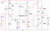
The spec's for the amplifier are a single -50V supply so of course the positive is ground.
"SPECS given: 50v single negative supply, 8ohm load, single transistor input".
0V should be gnd. C1 should be at the junction of the output transistor emitter resistors, and would isolate the speaker from the -25Vdc present at that point. in power amp circuits power supply rails are assumed to have a low impedance to ground. one of the rails, being 0V in this case should also BE ground. caps isolate the DC potentials at the input and output. there are stranger designs out there that work (but don't look on paper like they could work). matter of fact, i will start a separate thread about one of them, and you'll see what i mean.
It's a very confusingly drawn circuit, it's blindingly obvious from the spec that ground is the positive rail - he's just missed the symbol off of it (hopefully). But more important is that he's drawn the circuit 'upside down' - for a negative supply the negative should really be at the top, and the positive (ground) at the bottom - having the ground symbols pointing down, while the ground is 'up' makes little sense.
It's a very confusingly drawn circuit, it's blindingly obvious from the spec that ground is the positive rail - he's just missed the symbol off of it (hopefully). But more important is that he's drawn the circuit 'upside down' - for a negative supply the negative should really be at the top, and the positive (ground) at the bottom - having the ground symbols pointing down, while the ground is 'up' makes little sense.
Hee, hee.
He is in South Africa? Like in South America, Australia or New Zealand (down under). Isn't everything upside down?
He is also hot in winter and cold in summer.
Hee, hee.
He is in South Africa? Like in South America, Australia or New Zealand (down under). Isn't everything upside down
He is also hot in winter and cold in summer.
-50V Single negative supply- 8 ohm load- single transistor input
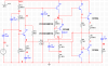
Made the changes. {i planned to tie all GND to 0V on the other cct (i just drew the cct like that)}....but anyway, its clearly shown on this diagram. Tomorrow I am going to collect the kit for building the amplifier.
How do i calculate the value of the compensation capacitor, C6?
Made the changes. {i planned to tie all GND to 0V on the other cct (i just drew the cct like that)}....but anyway, its clearly shown on this diagram. Tomorrow I am going to collect the kit for building the amplifier.
Looking better, but you've added a number of mistakes, check the feedback circuit (wrong way round, and joined where it shouldn't be), and whta's with C6?.
R15 sould be removed and a resistor to ground should be at the collector of Q7 as its load and to turn off Q5 quickly.
Q6 is upside down.
R6 and R7 should be a trimpot to adjust the output idle current.
The values for R3 and R4 are much too low.
It gives me "the creeps" to see an amplifier with a single negative supply. All the transistors appear upside down.
Looking better, but you've added a number of mistakes, check the feedback circuit (wrong way round, and joined where it shouldn't be), and whta's with C6?.
Are you sure Q6 is upside down?I had it connected the same way on the original cct.
& R3 and R4 are also the same vales from the other cct.
peak current=2.75A
The current through the resistor(R3 & R4) was chosen to be 10% of the max base current in Q1 :
IB1 (MAX) = (peak current/worst case beta of Q1) x 0.1 = (2.75A / 20)x0.1=13.75mA .
10% is chosen so that at maximum peak output current, there is a minimal volt drop.
using ohms law V=IR V=1V I= 13.75mA hence R3=R4=72 Ohm
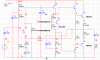
Made the changes. Yeah the circuit does look creepy with a negative supply. I had to think Upside down which is pretty confusing but its good mental exercise.
10uF for C6 is way too big. It won't pass audio.
You have the base of Q4 connected to the output rail.
Q5 has 625 mA into its base, via R15 regardless of the state of Q7.
R15 must be rated at 31.25 watts or more.
Bass response will be weak with only 1mF (1000 uF) for C1. Beware mF (milli farad) is technically correct but confusing.
Capacitors greater than a microfarad are probably going to be electrolytic, so you need to show their polarity.
If there are other problems we will have to wait until the smoke clears.
but Audioguru said that C1 is needed to block the 25V DC from this single supply amplifier. It should be about 1000uF for -3dB (half power at 20Hz into 8 ohms).
but Audioguru said that C1 is needed to block the 25V DC from this single supply amplifier. It should be about 1000uF for -3dB (half power at 20Hz into 8 ohms).
C1 should be somewhwere in the neighborhood of 3300uf to 10,000uf. C6 should be between 22pf and 100pf, and may need to be changed according to how the amp behaves under load. you need a current return between the emitter of Q7 to ground, and get rid of R15, it's saturating Q6.
1000uf is fine for C1 unless the amplifier is for a sub-woofer that must have a flat response down to 16Hz (-3dB at 3.2Hz. Then C1 should be 6000uF.
R3 and R4 should normally have just the leakage current of the output transistors in them plus a little more current when they have about 2V across them. They can be 1k ohms.
R6 and R7 must be a trimpot to adjust the output idle current for class-AB. Now it will probably operate in class-A which makes a lot of heat all the time.
R15 is still connected to the wrong rail. And 640 milli ohms is way too low, no matter where it is.
And the base of Q4 is still connected to the output node. You've just made it a more interesting spiral, but you've left it connected!
C1 should be somewhwere in the neighborhood of 3300uf to 10,000uf. C6 should be between 22pf and 100pf, and may need to be changed according to how the amp behaves under load. you need a current return between the emitter of Q7 to ground, and get rid of R15, it's saturating Q6.
This site uses cookies to help personalise content, tailor your experience and to keep you logged in if you register.
By continuing to use this site, you are consenting to our use of cookies.