Continue to Site

Welcome to our site!

Electro Tech is an online community (with over 170,000 members) who enjoy talking about and building electronic circuits, projects and gadgets. To participate you need to register. Registration is free. Click here to register now.

  • Welcome to our site! Electro Tech is an online community (with over 170,000 members) who enjoy talking about and building electronic circuits, projects and gadgets. To participate you need to register. Registration is free. Click here to register now.

Alternator and poles

Status
Not open for further replies.
Not true, BLDC normally wound in delta, but if wound in star you do not have access to the star point, so what do you use as a reference point to decide it is varying DC?
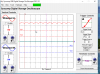
If you set up a virtual zero (Y) point by connecting three resistors, say 1k to 10k from each phase and connect the other ends and use this as a virtual zero, you will measure 3 distinct AC phases WRT zero, as shown on the PDF I posted.
Max.

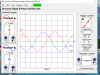
After thinking about what I said about the BLDC, while it would/could be considered AC it definitely wouldn't be sine wave AC, it would be square wave AC. This is due to the way the stator poles react with the magnets. In a car alternator it is sine wave because of the winding pattern of the stator and the "V" shape of the rotor poles.
 
Look at the PDF again on post #32. Done this many times when confirming the hall effect associated with a particular stator phase on a BLDC motor.
I back feed the motor at around 100rpm, then scope the hall and the generated output on a D.B. 'scope.
The out put is as shown, I use the resistor set up as described to provide a virtual zero or neutral.
If you have a BLDC motor and a 'scope, you can confirm it
Max.
 
martino I did a few tests on the one I have dismantled on the bench, it is a GM-Delco older style alternator, it has 12 rotor poles and a Delta connected armature (stator) consisting of 3 sets of 12 coils between each phase with a total of 36 poles faces.
Each field pole sits under 3 armature faces.
The field is ~2 Ω and the new brushes are ~1Ω ea.
With 2.5 amps to the field I was surprised on the apparent pole strength.
Once I get it reassembled I am going to try and get it to self excite using field residual, so that no external power is needed.
Max.
 
Max, after you get it assembled, if you could look at the stator voltage waveform before it's rectified, that would be of interest. :)
 
Thank You Max, also the waveform after the full rectifier should be interesting, to evaluate the amplitude of the ripple and its frequency.
 
Max, after you get it assembled, if you could look at the stator voltage waveform before it's rectified, that would be of interest. :)
Yes, I intend to, the stator has to be unsoldered from the bridge anyway, in order to dismantle.

Thank You Max, also the waveform after the full rectifier should be interesting, to evaluate the amplitude of the ripple and its frequency.
Can do, although the frequency and % of ripple on a 3ph full wave bridge is fairly predictable.
Max.
 
Here is the results of the alternator output when 2 amps is fed to the field, both monitor of two phases and the resultant rectified DC at approx 1880rpm.
Max.
 

Attachments

  • ALTDC.png
    ALTDC.png
    81.7 KB · Views: 274
  • ALTERNATOR.png
    ALTERNATOR.png
    116.5 KB · Views: 278
Status
Not open for further replies.

Latest threads

New Articles From Microcontroller Tips

Back
Top