Electro Tech is an online community (with over 170,000 members) who enjoy talking about and building electronic circuits, projects and gadgets. To participate you need to register. Registration is free. Click here to register now.
Welcome to our site! Electro Tech is an online community (with over 170,000 members) who enjoy talking about and building electronic circuits, projects and gadgets. To participate you need to register. Registration is free. Click here to register now.
no, you aren't getting 675 ips. you probably forgot the threads per inch of the lead screw. Lets says its 12 tpi, then you would be seeing 60ish IPS which is pretty good. I suspect loading or resonance will kick in somewhere.
I'm using byv27....
but with 31dq10 is better... or 1n5822
Matilda said:
I also kept the grounds isolated.
As in,
To the A3977 I have 5V & 24Volts going to the chip.
Pins 44,1,2 22,23,24 33,34,35 are connected to the 24V supply ground.
Pins 11,12,13 are connected to the 5V supply.
With the chip off the board, these two ground paths are isolated.
The chip connects them internally.
That was a tip from Allegro. It really helped minimize noise seen on the 5v and 24V supply lines while the motor was running.
my driver is work... with 3A... constantly with 2,8A (and BIG radiator)
but when motor in motion some faulty steps will accur ...
with smaller current too
A little update.
With a little help from the folks at Allegro, I found the best thing to do was adjusting the RC components while scoping current on one of the motor windings.
The default components for the RC fromAlllegro is 30K & 0.001uF.
By messing around I found that having a 10K & 0.01uF gave me the best run for my money. REF is set at 2.2V & PFD at 3.1V.
According to Allegro, the 10K & 0.01uF I have chosen are in range for RC values, but since my motor is a little big (10mH), it has all worked out.
Scoping. I was scoping motor windings with locked rotor.
Zoomed right in on flat portion of the STEP, and adjusted the PFD for expected sawtooth waveform.
Motors are back to being a little noisey. And thats because the end user had asked me to cranked up the torque. And as the formalua goes, I get 2.2V for the REF. As I turn down the ref, and thus lowering torque/holding power, the noise slowly dissapears.
My end user will have to determine what sort of torque he wants....and put up with the noise.
I believe we may solve this audible noise problem by giving away a free radio with every purchase!
MarkComp77,
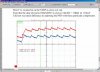
I've taken a screen shot of my engineering report for the project binder.
Here you will see I have scoped a motor winding.
Rotor locked.1/8" step.
Your looking at a step.
It IS! There've been a couple of times where the existance/absense of that barely audible, high-pitched hum has made me stop, think for a second, and take a second glance at the cutoff switch - just in time to prevent me from doing something stupid...
MarkComp77,
I've taken a screen shot of my engineering report for the project binder.
Here you will see I have scoped a motor winding.
Rotor locked.1/8" step.
Your looking at a step.
1. Yes, we are looking at the current waveforms through a winding.
2. 50A scale, but the current probe was probably set on (100x)
3. The two waveforms you see are not referenced to the same zero axis.
I moved them so they wouldn't lie on top of each.
My VDD is 5V. And my PFD is at 3.1V.
Slow decay is weak, but the motor runs best there.
I had a quick look at your motor. Looks like it has more torque than mine.
My end user has asked us to look into changing the motor. It was recomended I use Hurst & Airpax.
yes... my mistake
1.05V < PFD < 3V - mean mixed decay for a3977
---
Some time ago, I have changed project of driver's PCB.
I have added transoptors on inputs.
Now it is cooler radiator
I carry all tests at Itripmax=3A step=1/8 Vbb=32V
I'm curious to know what size motors people here are using on their A3977. I'm using a NEMA 23. 10mH, 1.4 Amps.
I hooked my motor up to a "complete" stepper motor drive, I'm still curious to know how to get the power/torque, and lower that annoying whine while sitting still! 4 motors at once is very annoying.
Is the motor noise something that bothers most?
Anyway, I found out that this stepper drive only powers one of the windings to the stepper when there is no STEP. A low DC voltage.
This keeps the motor quiet and cool.
This stepper drive also has ramp up speed.
So, if I try and feed it a 2khz STEP, it brings the motor up to speed quickly and smoothly. While the A3977 trys to hammer the stepper hard at the 2Khz signal. I do find the A3977 throws the stepper around pretty hard.
This is not to say that the A3977 can't do this, it can, but it takes some work. For example, if you have the I/O, you could vary the REF input to the A3977 while sitting still. When still, or no STEP, you could turn the REF right down.
Try this, power up your board, and enable the motor. Start turning down the REF value and you will hear the noise from the motor slightly dissappearing.
Also, control the frequency of the STEP signal, from a start.
RAMP the STEP signal up.
Remember, I'm not a pro!!
I'm just learning this as I go.....and sharing what I learn.
If you have anything to add....please let me know!
I use stepper motor 2.8A, 3.6mH - this need 10/20k & > 1.5nF **broken link removed**
I connected small motors too:
sanyo denki 103g771-0611 1,82A
sanyo denki 103-771-1242 1.35A
this work with 10k/1n (51k/1n <- pminmo settings for Rt/Ct)
Matilda said:
I'm still curious to know how to get the power/torque, and lower that annoying whine while sitting still!
I've been having issues with the allegro A3977 dying for no reason.
Never dies during use, I just found the system down.
I've been going through chips and wasn't sure what was happening.
I think I've just figured out what's going on.
My board has 4 A3977's driving 4 steppers. (10mH each).
When I have the board powered up (24V) and the A3977 is not enabled, I find that moving the steppers around by hand is killng the Allegros.
Moving the steppers around on the carriage also trips the 24V power supply that drives my Allegro board. While I had a meter monitoring VBB-24V I saw the meter jump to 56V and 61V....
So in short, moving the steppers around brings inductive noise back into my board.
When the motors are enabled, this doesn't happen. mind you when the motors are enabled their not easy to move.
Got any tips for me?
Can you point me in the direction of some lite reading material on the subject in question.
Driving the shaft of a stepper motor will generate a lot of back-emf. I think the standard approach is to disconnect the motor from the driver completely. I don't have any references available, but I'm pretty sure back driving steppers is one of those "don't do that" things...
A modification might be to throw in a transistor/resistor/zener diode combo to clamp the supply rail to a maximum value to prevent the 3977's from dying from overvoltage. I think they're sometimes refered to as braking resistors. Obviously this will appear as drag when moving the stuff around - so it's probably better to just disconnect the windings.
The steppers are driving a gantry system thats about 4' by 4'.
When the user wants to bring the steppers home, they believe grabbing the steppers and pulling them home is fast and safe.
I'v mentioned disconnecting the steppers from the system for this action, but they don't seem to listen!
markcomp77, in regards to the schematic you have there.
Is the T1 line the VBB?
Also, I was looking at the other schematic you posted earlier. It shows two diodes and a TIP41...is that performing the same job?
And finally, what's the purpose of the 8 BYV diodes?
I thought they would have handle the back-emf?
This site uses cookies to help personalise content, tailor your experience and to keep you logged in if you register.
By continuing to use this site, you are consenting to our use of cookies.