Electro Tech is an online community (with over 170,000 members) who enjoy talking about and building electronic circuits, projects and gadgets. To participate you need to register. Registration is free. Click here to register now.
Welcome to our site! Electro Tech is an online community (with over 170,000 members) who enjoy talking about and building electronic circuits, projects and gadgets. To participate you need to register. Registration is free. Click here to register now.
You did not follow the instructions on the datasheet of the LM2936 linear low dropout voltage regulator. It says IT MUST have a certain type of output capacitor (an ESR within the range shown) and it should have an input capacitor. Its maximum output current is only 50mA and you said the mini-DVR (that has no part number) draws 800mA.
A low dropout regulator always needs a certain ESR on its output capacitor but your circuit does not need low dropout, an ordinary 5V regulator with almost any output capacitor will work if it can supply the current used by the mini-DVR.
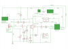
I'm not using an LM2936. I have changed the label to the actual IC mounted on my step down regulator, which is
MP2365DN.... the audio/video recording went very well on Mon & Tues so I have not added a capacitor to in/out of the step down regulator for now. Thanks.
Not so fast !! On Mon & Tues, I was testing the whole circuit that included audio, video and recording, but was still using separate batteries to supply power. I still need to add R1, R4 & C8 to see what happens when using one 12V battery... If the circuit works (no audio noise) now with one 12v supply, I will then test it using (3) 18650 batteries which may end up being the power supply for this design. I am making the changes tonight and should have results soon....
By the way, I am adjusting the gain from around 45 to approx 21 so I can record normal voice(s) and noises clearly. The gain was way too sensitive for testing purposes. A slight breeze sounded like electrical noise and it recorded my friend and I loudly, but clearly, from over 20' away. In fact, as we were talking loudly while riding on an ATV to check targets at 100 yards away, it recorded parts of our conversation over the noise of the ATV's motor!! This is definitely an awesome sound circuit. When the testing is done, and the mic is installed properly in an enclosure I will up the gain again to capture the sounds of the wildlife around the feeder. That higher gain level will also be used for recording from the hunting blind which will be a very low whisper for commentary. I can't thank you enough for guiding me through this very complicated task.
Since the sensitivity to loudness of our hearing is logarithmic (so we can hear very weak sounds and also hear very loud sounds) then doubling or halving gain (45 to 21) makes a small change. 10 times the level sounds twice as loud. 1/10th the level sounds half as loud.
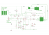
Ok, I tested my circuit as shown below.... I used one 12v AGM 7ah battery. I added the filter consisting of R4, R1 & C8. I also changed R3 from a 2.2k to 4.7k resistor to reduce sensitivity. HUGE improvement from using one battery without the filter last weekend !! I got clean video and good audio. I still have a minor electrical noise like a steady rapid 'tap' in the background. Maybe making an adjustment in the filter could eliminate that altogether? I believe it's coming from the camera/monitor. I'm very pleased to get this result from the one 7ah battery. Now I will build a new board that is better organized and cleaner than the 'Frankenstein' board I ended up with and will use 11.1v from (3) 18650's in hopes to have a self contained rechargeable system. I see no need for adjustment in my circuitry based on the 11.1v revision. Please correct me if I'm wrong... thanks.
Since the sensitivity to loudness of our hearing is logarithmic (so we can hear very weak sounds and also hear very loud sounds) then doubling or halving gain (45 to 21) makes a small change. 10 times the level sounds twice as loud. 1/10th the level sounds half as loud.
Very good to know. Thanks for explaining that. I noticed the result was a subtle change in sensitivity, but seems to be about right. A regular voice is clear now, but a whisper is still recorded clearly also. A regular voice 30cm away was garbling the signal before I changed the resistor to 4.7.
18650 battery cells are lithium-ion type. They are ruined and made dangerous to normally charge if they are discharged less than 3.0V per cell (which will happen). You need a circuit that monitors the battery voltage and disconnects it when the voltage drops below 3V x 3= 9.0V.
18650 battery cells are lithium-ion typdelivered ey are ruined and made dangerous to normally charge if they are discharged less than 3.0V per cell (which will happen). You need a circuit that monitors the battery voltage and disconnects it when the voltage drops below 3V x 3= 9.0V.
I plan to have a BMS board incorporated with the batteries. The board is expected to be delivered any day now. If it functions properly, I will order more. Thanks again for the heads up.. any other suggestions for managing the batteries is welcome of course.
Maybe a capacitor between the camera and monitor ground would get rid of the remaining 'tapping' noise in the circuit? That is where the noise was coming from previously.
I added the C1 capacitor to GND from camera and monitor. Will try this and see if tapping noise is eliminated. The 'tapping' noise I heard in my previous test using one 12v battery was detected on ear buds. The noise I got before adding the filter from the mic was also heard on the ear buds and was much more pronounced on the DVR audio recording, so I am assuming the tapping I am hearing now would be very pronounced also on a DVR recording. Once I get clean audio to the ear buds using one battery source (12v battery or (3) 18650's - 11.1v), I will test the recording on the DVR.
Should I expect any improvement by adding the C1 capacitor or are there any other suggestions?
Thanks.
Your C1 capacitor will filter the power supply voltage and if the voltage is fluctuating due to the camera or monitor then the filtering will reduce the level of the tapping sounds.
But the interference might be caused by resistance of the wiring (mainly the ground wire) which will have a voltage drop when a high current flows in it. Maybe the ground wiring thickness must be increased.
Proper grounding is usually using the "star" method where all grounds connect together at one point then there is no voltage drop fed to other parts.
Thanks AG. I will plan to connect ALL grounds together and add C1. Hopefully it will result in a clean audio recording. My 12v supply & ground wires are solid 22ga
Thank you.
I tested the circuit. I started with a .1uf capacitor for C1 (ground for camera and monitor). I got no video. I changed to a 4.7uf and got a poor signal to the monitor, no picture. Eliminating the C1 capacitor altogether from the camera/monitor ground gives me a good video result. Should I try the 100uf or larger capacitor at C1 as indicated in my schematic above? I am still getting noise in the audio, but it is not the 'tapping' I was getting previously. Now it is a slight buzz/humm/whine (best way I can describe it) in the background (as recorded to DVR), but my voice is coming through just fine. A modification to or additional filter should take care of the noise that is remaining.
Bottom line: Good video without C1 capacitor. Good audio except some background noise that can probably be filtered out somehow. Results were recorded to DVR. I would appreciate any further instruction you may have to offer. Thanks again
You don't need C1, you need a straight wire from battery minus to camera GND.
Same with monitor and buck converter.
All with separate wires to battery minus, a common ground point.
This site uses cookies to help personalise content, tailor your experience and to keep you logged in if you register.
By continuing to use this site, you are consenting to our use of cookies.
")

 On Mon & Tues, I was testing the whole circuit that included audio, video and recording, but was still using separate batteries to supply power. I still need to add R1, R4 & C8 to see what happens when using one 12V battery...