Electro Tech is an online community (with over 170,000 members) who enjoy talking about and building electronic circuits, projects and gadgets. To participate you need to register. Registration is free. Click here to register now.
Welcome to our site! Electro Tech is an online community (with over 170,000 members) who enjoy talking about and building electronic circuits, projects and gadgets. To participate you need to register. Registration is free. Click here to register now.
Anyone need an earthquake detector?
I must admit that I like your approach. You are forcing me to learn. I will study your comments and make some adjustments. Thanks.
BTW... the 11.9v was a brain fart. My brain has had a lot of gas lately.
Based on your description of how the circuit is functioning, if I change R16 to 200ohm and R15 to 10ohm, I would have a gain of 21 (1+R2/R1).
Is that correct? And that would mean that with the voltage in being 6v, the output is trying to be 186v.
Is that correct?
Why do you want to overload the output of the opamp with your VERY low resistor values of 200 plus 10 ohms?
Those resistors connect from the output of the opamp to ground (creating negative feedback) so then they are a load of 210 ohms. The datasheet of the OPA2134 and for every other opamp shows that when the load is 10k ohms or higher then the performance is fairly good. But is shows that when the load is 2k ohms or less then the performance (distortion) is awful and the opamp overheats.
You do not understand the importance of the capacitor in series with the feedback resistor to ground so I give up explaining the basics of electronics to you!
I have this posted on allaboutcircuits also.....
I have the circuit working on the breadboard now. I connected a 3.5mm jack socket and pair of earbuds (L&R) to the signal coming out of pin#1 on the opamp and GND connects to the same GND as others. After some minor adjustments, the audio coming out of this circuit is very sensitive and clean as was hoped for. I am very happy with that result. However, when I connect the 'audio in' from the DVR (powered by 5v via buck converter), instead of earbuds, I get a lot of noise recorded by the DVR. I can hear my voice mixed in with the noise, so I am getting a very dirty signal to the DVR, but need to know what needs to be adjusted to clean it up and hopefully record audio like what I was hearing on the earbuds. Still testing....
I am thinking that the gain has to be reduced considerably, so I am adjusting that now to see if it helps.....
BTW, I had R15 labeled wrong, it is a 1k.
Tried several things to get rid of the noise.... I decided to hook up a 9v battery to supply the DVR (stepped down to 5v) separately. I got perfect audio recorded to the DVR !! It sounds really clean with zero noise. Is there anything I can do to supply my DVR's buck converter with the 12v supply and get rid of the noise?
I would like to avoid having to add a separate power supply for the DVR. Is there a way to filter out this noise?
A buck converter efficiently reduces the voltage by oscillating which creates noise. A linear voltage regulator like a 7805 reduces the voltage but wastes power by making heat but it produces no noise. The datasheet for the 7805 shows an important input capacitor and an important output capacitor. Depending on how much current the DVR uses a lower power 78M05 or a small 78L05 can be used.
A buck converter efficiently reduces the voltage by oscillating which creates noise. A linear voltage regulator like a 7805 reduces the voltage but wastes power by making heat but it produces no noise. The datasheet for the 7805 shows an important input capacitor and an important output capacitor. Depending on how much current the DVR uses a lower power 78M05 or a small 78L05 can be used.
Thank you AG. I am getting very good results to the DVR now, but it is only by using a separate 9v battery to power the DVR. The only wire from the DVR touching the preamp circuit is the audio gnd to the pre amp circuit's gnd. I remember you explaining that was the ground shield. It's a good thing because I was isolating it altogether and got a high pitched squeal. As soon as I corrected the gnd, it sounded great. I will look into the 78x05's you're talking about as I would like to avoid the need to use the 9v batt in my design. I appreciate all of your help.
BTW, I believe the current may be 800ma. I have not been able to find a definite answer though.
A 7805 is in a case with a metal tab. The metal tab can be screwed to a heatsink to cool the device. The heat is caused by the voltage from its input to its output times the current in it so if the input is 12V and the current is 800mA then its heating is (12V - 5V) x 800mA= 5.6W. If it is in 25 degrees C air and is not enclosed then it will overheat and fail if it dissipates more than 2W without a heatsink. It is rated at 1A but most can produce 1.5A.
A 7805 is in a case with a metal tab. The metal tab can be screwed to a heatsink to cool the device. The heat is caused by the voltage from its input to its output times the current in it so if the input is 12V and the current is 800mA then its heating is (12V - 5V) x 800mA= 5.6W. If it is in 25 degrees C air and is not enclosed then it will overheat and fail if it dissipates more than 2W without a heatsink. It is rated at 1A but most can produce 1.5A.
Good to know. I did more testing (suggested by jjw on allaboutcircuits) and regardless of whether I use 9v or 12v, I get the noise. However, the noise goes away as soon as I disconnect the pos/neg leads from the DVR. I tested this with and without the aud-in/out connected also. Same result. If I have the DVR supplied with the same power as the circuit, I have noise. The audio is perfect without the DVR connected, or DVR supplied by separate battery source. I think that I would rather use a separate source for the DVR (9v batt) than have to create additional circuitry and burn 5.6W of juice while needing a heat sink also.... do you agree?
You said the DVR current might be 800mA. But an ordinary 9V alkaline battery is dead in 1 hour at only 250mA and might not produce 800mA for only a few seconds. Six AA alkaline cells produce 9V but at 800mA they are dead in about 1.5 hours.
Maybe your noise is caused by feedback from the power supply into the mic preamp. The resistor that feeds the microphone must be fed from a filtered voltage, not directly from the power supply that might have its voltage bouncing up and down a little with noise or the signal.
I question the 800ma, but your point is well taken. That would not work. So how would I go about setting up a filtered supply to the mic? Can that filtered supply come from the same 12v battery that is supplying everything now? Job for a capacitor?
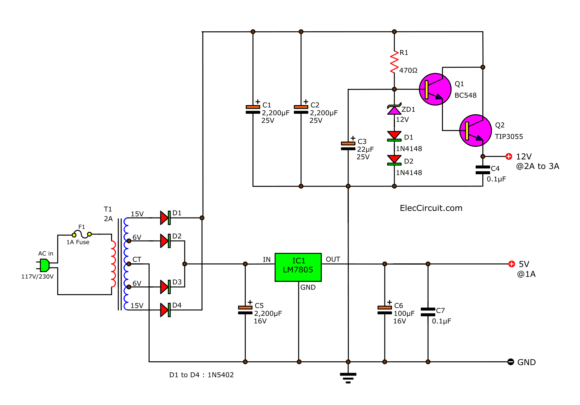
I ran across this while looking up 12v circuit filtering. It appears that I could put 12v in and get my 5v and 12v from the same 12v battery (7Ah). Is this something to consider, or should I avoid it altogether.
With an input of 12.0V then the 2N3055 transistor and the 12V zener diode do almost nothing. They produce an output of 11.3V when the output current is only 160mA, the input is 13.2V and the 2N3055 has low current gain. The 5V regulator works well with the original 12V as its input. Why do you need 12V to be regulated?
The LM309k and 2n3055 are in huge steel old fashioned packages.
Your last schematic showed the microphone powered with a 22k resistor from 12VDC. But the microphone's current is about 0.5mA and might be a little more at 0.6mA. Then its power supply must be higher than (0.6mA x 22k) +1.5V= 14.7V so the 22k resistor value is much too high.
A 4.7k resistor from +12V with 0.5mA in it produces 9.65V and a 10k resistor feeding the mic will produce 4.65V across the mic so it does not produce distortion when sounds are loud. The 9.65V junction of the two resistors will be 9.18V when the mic current is a little high at 0.6mA which is fine. The junction of the two resistors can be filtered with a 100uF capacitor to ground. But if the DVR is powered from the 5V regulator then the mic can also be powered from the 5V regulator through a 5.1k or 4.7k resistor.
With an input of 12.0V then the 2N3055 transistor and the 12V zener diode do almost nothing. They produce an output of 11.3V when the output current is only 160mA, the input is 13.2V and the 2N3055 has low current gain. The 5V regulator works well with the original 12V as its input. Why do you need 12V to be regulated?
The LM309k and 2n3055 are in huge steel old fashioned packages.
'jjw' over on allaboutcircuits made the suggestion to reduce noise I was getting by using a common voltage supply for everything while incorporating a linear regulator.
jjw also said: "supply the mic+ amp with separate 9V battery
and the buck converter from 12 V
Probably it won't help, but if it works, you can supply the mic+opamp from 12V to linear ( about 9V )regulator.
No heatsink is then needed because the mic and opamp need very small current."
Your last schematic showed the microphone powered with a 22k resistor from 12VDC. But the microphone's current is about 0.5mA and might be a little more at 0.6mA. Then its power supply must be higher than (0.6mA x 22k) +1.5V= 14.7V so the 22k resistor value is much too high.
A 4.7k resistor from +12V with 0.5mA in it produces 9.65V and a 10k resistor feeding the mic will produce 4.65V across the mic so it does not produce distortion when sounds are loud. The 9.65V junction of the two resistors will be 9.18V when the mic current is a little high at 0.6mA which is fine. The junction of the two resistors can be filtered with a 100uF capacitor to ground. But if the DVR is powered from the 5V regulator then the mic can also be powered from the 5V regulator through a 5.1k or 4.7k resistor.
I like the idea of powering the mic with the 5v. So, I would have the DVR & mic on a regulated 5v supply (4.7k resistor before mic) and the opamp on the 12v battery supply.... Maybe that would also solve my noise issue and eliminate the need for a separate 9v battery?
I also have the option of supplying everything with 7.4v using two 18650 li ion rechargeable batteries.... would 7.4v to the opamp work as long as I divide the voltage to 3.7v+ into pin3? That could be the solution to this altogether. I'll check the opa2134 data sheet.
It looks like 7.4v would work for voltage to pin8? Would this be a viable option? And, if so, am I correct in assuming a runtime of approx 3.5 hrs? My 18650 batteries are 3.7v/3000mAH.
An electret mic is not an LED. An LED sets its own voltage but the resistor value, the supply voltage and the current draw of an electret mic sets its voltage that your calculator did not calculate.
You calculated 19k ohms but used 22k ohms so if the mic current is 0.50mA then the voltage across the 22k resistor is 0.5mA x 22k= 11V so the mic gets only 1.0V and barely works. If the 22k resistor is 5% high at 23.1k and the 12V is 5% low then the mic gets no voltage and does not do anything.
Most electret mics have a maximum voltage rating of 10V so why not use a 15k resistor so that the mic has 4.5V across it?
I like the idea of powering the mic with the 5v. So, I would have the DVR & mic on a regulated 5v supply (4.7k resistor before mic) and the opamp on the 12v battery supply.... Maybe that would also solve my noise issue and eliminate the need for a separate 9v battery?
This site uses cookies to help personalise content, tailor your experience and to keep you logged in if you register.
By continuing to use this site, you are consenting to our use of cookies.


")