Electro Tech is an online community (with over 170,000 members) who enjoy talking about and building electronic circuits, projects and gadgets. To participate you need to register. Registration is free. Click here to register now.
Welcome to our site! Electro Tech is an online community (with over 170,000 members) who enjoy talking about and building electronic circuits, projects and gadgets. To participate you need to register. Registration is free. Click here to register now.
It isn't specifically for stereo, and AG never suggested it was, he merely asked if your mike was stereo as you were choosing a dual opamp.
You can use just one of them if you wish (ignoring the other), but it's rather a waste - you could use the two for stereo, or use the two for different purposes.
Good news, thanks. Can I attach two mics and get stereo? I didn't mean to come across the wrong way. My frustration level is up as I am in very unfamiliar territory. I am a structural engineer.
I will try the transistor circuit first and if that has too much noise for what I am expecting, I will build a new circuit with the OPA2134 opamp.
Thanks again.
Use a stereo mic if you have two heads that are both talking or singing at the same time.
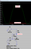
A single transistor used as a preamp gives pretty bad distortion, even if you are lucky to find a "typical" one. If yours has a low or high current gain then its distortion is much worse.
Here is a simulation with a fairly loud mic sound and you can see the distortion on the sinewave that will sound awful. An audio opamp will produce extremely low distortion that cannot be heard.
Use a stereo mic if you have two heads that are both talking or singing at the same time.
A single transistor used as a preamp gives pretty bad distortion, even if you are lucky to find a "typical" one. If yours has a low or high current gain then its distortion is much worse.
Here is a simulation with a fairly loud mic sound and you can see the distortion on the sinewave that will sound awful. An audio opamp will produce extremely low distortion that cannot be heard.
Your opinion is valued and the .png file shows a great visual of what is happening when using a transistor.... I am expecting the OPA2134 op amps to come today and will redo my schematic to utilize that IC. I am developing a product and want quality, low noise, so I will quit messing around. Thanks again for all of your help and patience.
I just copied this from the web: Is it a good starting point?
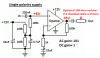
Your mic is connected completely wrong. Its case and ground wire should be connected to ground and its output is its (+) pin that should have a 4.7k resistor connected to a filtered +5V source. You have the mic doing nothing and the opamp is amplifying noise on the +5V supply.
Why does your opamp have a 1k input resistor that is not needed?
You show two opamp circuits with a single polarity +12V supply but both opamps inputs are biased at 0V instead of at half the supply voltage. Then your opamps only amplify inputs that swing positive and do nothing when the input swings negative so they rectify the audio creating severe distortion.
Why is the output resistor 1k or 1.5k instead of 100 ohms if it drives the capacitance of a shielded cable? Why do you have R14 and R15?
Why is the voltage gain of your circuit only 2 instead of amplifying the microphone's tiny output 100 times?
You show one opamp of an OPA2134 dual opamp. What will you do with its second opamp to prevent it from oscillating and causing interference?
The high stray capacitance between the rows of contacts and wires all over the place on a solderless breadboard will probably cause modern high frequency opamps to oscillate and cause severe distortion. Use a compact pcb or stripboard instead.
I obviously have a lot of work to do...... I was searching online images of 'OPA2134 pre amp circuits' and this one was described as an appropriate option, or so I thought. Thank you for the attachment to go by. I will post my schematic when finished.
Here's what I have at this point.... what is left to get this circuit to produce clean audio for me? I will build this on a solderable bread board once it is correct.
I have the 'other half' of the OPA2134 in the plan now, but do not want to guess at what to connect to where to render it neutralized.
audioguru,
You wrote in an earlier thread "The black input wire of the DVR audio input is the ground of the preamp and it is the shield of the connecting cable."
Should I ground the mic to the 5v battery supply and all other grounds to the audio in (-) on the DVR like this?
audioguru, I stumbled onto your TL071 circuit on the allaboutcircuits website. If I purchased some TL071 opamps and built this circuit, would it send a clean signal to my mini DVR recorder? I understand I would need to make a few minor adjustments based on my mic and the DVR, etc..., but is this the circuit I should be using?
I do not know why you miss things when you copy my simple circuit. Your image from allaboutcircuits does not work.
You show an OPA2134 DUAL opamp that has two opamps in it, instead of using an OPA134 that has one opamp in it. A TL071 can use the same circuit but the OPA134 is newer and better.
[Quote/] 1301644, member: 16360"]I do not know why you miss things when you copy my simple circuit. Your image from allaboutcircuits does not work.
You show an OPA2134 DUAL opamp that has two opamps in it, instead of using an OPA134 that has one opamp in it. A TL071 can use the same circuit but the OPA134 is newer and better.[/QUOTE]
I may miss something because I am not a guru like you. I am trying to follow the best I can.
You should read the thread again. I explained why i am using the opa2134 already. Will you tell me why the circuit won't work? Or, can you tell me specifically what it needs to make it work? I'm going on two weeks now trying to decifer how to get a simple electret mic to send an audio signal to a dvr. Who knew it would be this diffucult?
I do not know why you miss things when you copy my simple circuit. Your image from allaboutcircuits does not work.
You show an OPA2134 DUAL opamp that has two opamps in it, instead of using an OPA134 that has one opamp in it. A TL071 can use the same circuit but the OPA134 is newer and better.
I just looked at your markup........ thank you very much. As soon as my opamps arrive, I will test it on the breadboard and post results. Please forgive my frustration.
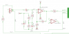
Don't you understand that your opamp circuit had a DC voltage gain of 1 + (10k ohms/100 ohms)= 101 times? The (+) input is +6V so the output is trying to be +606V but it can't so instead it is saturated as high as it can go and then the opamp does not amplify the signal. The missing capacitor to ground in series with the 100 ohms resistor will not pass DC so the DC gain of the opamp circuit will be 1 and the output voltage will be +6V so that it can swing up and down with the amplified signal.
Don't you understand that your opamp circuit had a DC voltage gain of 1 + (10k ohms/100 ohms)= 101 times? The (+) input is +6V so the output is trying to be +606V but it can't so instead it is saturated as high as it can go and then the opamp does not amplify the signal. The missing capacitor to ground in series with the 100 ohms resistor will not pass DC so the DC gain of the opamp circuit will be 1 and the output voltage will be +6V so that it can swing up and down with the amplified signal.
No, I don't understand. I am a structural engineer. I am looking for solutions and that is why I am asking specifically how to make this circuit work. This is my latest 'guess':
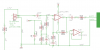
Where do you get 11.9V?
With a 12V supply, the datasheet for the OPA2134 shows that its input cannot work if it is higher than 9.5V and its output cannot go higher than 10.8V. You need its output to idle at half the supply voltage so it can swing equally up and down with the signal.
Since R15 now has a capacitor in series with it the DC voltage gain of the opamp is 1 so its output idles at +6V. The AC voltage gain is now 1+ (13k/2.2k)= 6.9 times which is probably much too low and the 2.2k resistor with a 22uF capacitor allows the opamp to amplify earthquake frequencies as low as 3.3Hz.
This site uses cookies to help personalise content, tailor your experience and to keep you logged in if you register.
By continuing to use this site, you are consenting to our use of cookies.