Electro Tech is an online community (with over 170,000 members) who enjoy talking about and building electronic circuits, projects and gadgets. To participate you need to register. Registration is free. Click here to register now.
Welcome to our site! Electro Tech is an online community (with over 170,000 members) who enjoy talking about and building electronic circuits, projects and gadgets. To participate you need to register. Registration is free. Click here to register now.
Do your lights flicker just before the breakers trip?
If so the high frequency box could be causing your SCR driver circuit to false trigger on one half of the waveform at times basically making the welder into a high current DC biased short on the lines.
It's definitely a filtering problem and I suspect that both the HF box and your circuit need better shielding and filtering to keep the noise where it belongs.
It's the only way I can immediately think of that could pull that much current to trip main breakers loaded or otherwise.
Lights (older fluorescent ) flicker whenever hi frequency box is on. Always have. I have had it all running at once before, when I had no power control circuit going and never blew the breaker. Today, I welded steel (no hi frequency) and never blew any breakers so reassures me I need to figure out a filter. I instance MOVS in the welder where the power comes in, from each hot to chassis. Welded for a while, then main breaker in house went.
The cover is off the welder so perhaps it would help to put it back on. That would at least enclose the transformer in a steel box but the hi frequency is introduced to the welding cables outside of the welder, ie hi frequency box plugs into welder jacks, then welding cables into the box. Reading your reply again, maybe the cover is important. I might need to consider putting the control circuit into a box of its own, within the welder too...mmmmm
MOV's knock down high voltage spikes but are not a good bypass for lower level high frequency noise.
Low ESR capacitors that channel that noise to solid equipment and wiring system ground planes are what's need for that.
I would start with putting .1 and .01 uf ceramic capacitors between and across every power input and work output line and the equipment frames plus make sure you have a good solid earth ground close by on your electrical power side that ties all the equipment together as well.
That and putting the covers on will help keep the RF noise from bleeding out and into things through the air considerably.
You are smart.... ;-) I am still beating myself up....not so smart...
Installed .1 uf caps from power in lines to the chassis of the welder (at the switch but before) I did not put a cap between them though so will go try that now. Welder chassis is grounded. Closed up all covers. Wrapped foot pedal cord in aluminum tape as it was not shielded and this tape goes under the cable clamp at the welder so the shield should be at a ground potential. I did have a bare copper braid wrapped around the foot pedal cord and the new tape encloses all of this. The braid is grounded too. I taped some of the ground and electrode wires together as suggested from the other forum posting. Tried laying out welding cables around floor whereas before they were kind of a loose loop.
And still blowing the main breaker feeding the shop (in house, over 100 feet away) I just say this as the breaker in the shop is not blowing nor is the welder breaker which is a 40 or 50? Need to go look. The main breaker is a 60 Amp feeding the shop. Almost sounding now, as I type this, that maybe changing this main breaker would be a step...Although not sure why it only trips with the hi freq on unless, as you suggest, I am getting surges in the primary current draw.
The fluorescent light fixture in the shop still fluctuates when the hi freq is on. This to me indicates, either a hi freq being introduced into power line or that the emi(?) is strong in the shop.
Just an update. Will install a cap across the power lines.
I checked the other breakers. The shop main breaker is a 60 amp (westinghouse panel) and the welder breaker is a 60 Amp in that panel. The house breaker is a Square D 60. I did stumble across a comment on another thread about the Square D breakers having a different response curve. I am borrowing a clamp on ammeter and will check to see where the current is running at. Not sure if it will grab a max value for me yet though. I do suspect that shielding may be the issue but want to know if I may have a weak breaker before I go further with more capacitors. Starting to look like a frankenstein-welder.
At this point you probably need an O=scope to do actual visual monitoring of your power line voltage and current waveforms to see what going on with them.
Given the light flickering and continual breaker tripping I am half tempted to think have one half of the AC wave being triggered more than the other and that's causing a strong enough DC bias on the phase angle control to trip the breakers.
Also what do you have for noise bypass/snubber capacitors on your actual control board to keep its own DC power and reference point signal clean?
Any .1 uf ceramic or poly bypass capacitors right across the 555 IC power and ground pins and the power transformer secondary leads or on the foot control leads to drain any HF noise off them?
It's just a guess but that could be where the HF is leaking into the system and causing some timing cycle false triggering issues.
At least you are not blowing SCR's to bits any more.
Relating to putting bypass capacitors on things to shunt unwanted HF line noise away from critical parts of circuits, some years ago I had the original torch for my big Stak Pak plasma cutter burn out and the most cost effective replacement was a brand new torch and cord unit designed for there at the time brand new model of machines being the old machine I have as a whole was well past obsolete and no parts were to be had cheap plus it was just oversized and clunky to work with as well.
The problem was none of the new torch and cord units had ever been made to be reverse compatible with the old machine so when I put the new one on it bled loads of HF noise into it's trigger leads causing the plasma cutter to continual go nuts ans shut down. The simple fix ended up being nothing more than refitting tiny ceramic bypass capacitors between every torch lead control circuit wire and the main torch cord ground strap to knock that HF noise out before it got to the control board.
It's been that way for around 13 - 14 years now and hundreds of hours of cutting time and has yet to ever have a HF glitch since.
The only caps on the control board are what is on the schematic. With my current issues, it sounds obvious that I should have more.... I pulled the board out and will put some more filter caps on it. I was going to install one across the foot pedal today but wondered if it would affect my timing, seeing as it would be going exactly across the resistor that sets up my timing. C3 (timing cap) is .012 uf so to put a .1 across the control, I would think, would alter this circuit. Am I correct? Maybe a small one like .0047 uf? It has been 35 years since I had to do equivalent circuits.....
I can scope around the control board tomorrow. I hesitate to hook the scope up to the power line. Can't recall the rules about doing that but do recall blowing one up, once. I don't have an isolation transformer. I do have a generator I could run the scope on maybe....
The light flickers with only the Hi Freq box turned on. It shows how much noise it puts out there. I tried different receptacles but does not matter. Welder does not need to be on for this box to cause the light to flicker. Maybe I should be trying to contain the emi or rfi instead of controlling it after it gets into my control circuit? Hard to do though since the hi freq has to be super imposed on the welding cables to do its job of maintaining the arc.
I have attached an image of the last version I have installed.
I would put one across pin 1 and 8 of the 555 and one across the LM7812 input lead and ground and two across the transformer secondary leads and ground and see what happens from there.
As for your foot switch having one from the 12 volt lead to ground shouldn't affect anything and you could also install some inductors in series with the leads where they come into the circuit should help attenuate any RF noise they may be picking up.
I would also look at moving the R4 100K pot to the foot switch return lead instead of being between the 555 and the c3 timing capacitor as well. That could be where you are picking up a lot of your false triggering issues being the way you have it set up now would allow the threshold voltage to be easily influenced by noise from the footswitch leads.
Plus by having it there you could put a bypass capacitor on that lead without drastically affecting the timing cycle that's determined by C3.
Will do and report back. The 100k pot could probably be replaced with a resistor and I could put that in the foot pedal or easily move it on the control board. Timing seems good with it maxed out.
I have made some progress but not perfect yet. I did change R4 to a resistor and moved it as shown in the attached diagram. On this latest version, I tried to illustrate where I added ferrite beads, capacitors and MOVs. I perhaps should have ordered inductors...? I tried to find some information on choosing beads and inductors but don't think I have enough info to properly select one. If anyone can point me in a direction as to what part numbers would be appropriate, that would be appreciated. I tried to select ferrite beads that reacted with more resistance at lower frequencies. I do not know what frequency this box generates and with it being 3500 volts, not sure how to check it. I don't think it is near 100Mhz which seems to be the basis for many ferrite bead specs but I found some at 5 MHz so went with a selection of those. So as a wild card shot, I added some .1 uf caps, and a couple of ferrite beads. I changed receptacles for the hi freq box. I tried adding a dedicated ground rod outside and connecting it to the welding receptacle box. Tomorrow, I will try connecting the welder chassis to the ground rod.
One big issue I found was that my "ground" for the circuit (the circuit board is powered through a transformer so effectively isolated ) was not connected to the chassis ground of the welder....I had not thought to do that so I thought for sure that would be the ticket, but nope, no real difference.
Today, I set the scope to 10 mV per division (x10 scope so 100 mV) and had the probe from the circuit ground to the chassis ground. I registered a lot of noise here too ( I think it should have been zero unless the scope is picking up random emi....?) so not sure that any of my grounds are being effective. I have sanded paint off of connections and used external toothed lock nuts to cut into the metal. I added a .1 uf cap across the line supply in the hi freq box in an attempt to reduce a chance of the hi freq being back fed into the AC line.
....g and you could also install some inductors in series with the leads where they come into the circuit should help attenuate any RF noise they may be picking up.
.
Having said all of that, when measuring AC current with my new clamp on meter, the EMI is so strong in the shop that the ammeter reads 10 amps when the welder is not even plugged in so this input is unreliable. I was measuring at the junction box on the back of the welder where the line cord connects but now moved the ammeter to the circuit panel box. I think it is more reliable over there. I was able to weld for about a half hour today before the welder breaker went. A few days ago, I found the line connection at the shop breaker in the house slightly loose ( took a quarter to half turn) so perhaps some loss here, causing that breaker to go. The last few times, it was the welder breaker in the shop panel that went but as I do more things, it seems to be getting better. ie can weld longer.
I scoped Pin 3 of U3 and see some noise here with hi freq box on. Any ideas as to how to reduce it here or should I keep adding caps to everything?
Another thing to try tomorrow would be putting a box around the actual circuit board in the welder but I believe the noise is getting into the circuit through the welding leads since putting the cover on the welder does not seem to make a difference either.
It was fun for a while but is now just getting frustrating. Sorry for the long winded story but I am hoping someone sees something that might trigger the solution. I realize it is near impossible to do without being here.
There is a small section on filtering and it suggests a 6.3 uH choke. Something else for me to try. The article looks good for a newbie like me to noise suppression.
Well, I have almost given up on the AC Tig welding project. I have ordered some inductors and might try them but after so many hours this far, it might be time to cut my losses. Given the amount of interference the Hi freq box generates, it might never be usable with a power control. Having said that, I will probably look at it again sometime in the future. I would like to redo the pc board to incorporate the filter caps and new inductors rather than further modifying it.
Having said that, what I am really happy with is the control circuit. I modified the foot pedal again so that the welder can be used with a foot control, at full power or the foot pedal can be used as a remote power control and one that is easier to use than the slide control on the front of the welder. I installed a rotary switch that selects between the foot pedal pot, a fixed resistor of 10K (so allows virtually full power at the welder for stick operations) and another pot in the welder that can be used to dial in the power setting, much like the foot pedal does but adjustable on the bench. If you do not need to constantly vary the power, I figured a control on the bench beside you to vary power would be handy. Been playing with it tonight to see if my electronics blow up and so far, only smoke is from the weld. The pot is much more easily adjustable and convenient than the welder control.
For aluminum, I think I will just go with my spool gun on my Mig unit. To practice or do DC Tig, this modified unit will do the job. And now that I can just run full power with the flip of a switch, I have gained my stick welder back again. If you have been following along, you will note that once I installed the foot pedal control circuit, I would always have to have it depressed just to stick weld. Not always convenient. And the slide control on this unit is not as nice on a Lincoln Idealarc so having the extra control on the pedal is a nice option.
To use the remote function, I set my slide on the welder higher than what I would want, so say 180 amps for a 120 amp operation. Then I can dial in the 120 or more or less, should I change electrodes or diameters. Very sensitive and convenient.
Thanks tcmtech for all of your super support (and patience). Thanks to your prodding, and hints and outright direction, I learned a lot about AC control circuits and ended up with a gucci little welder (it is not a lincoln but it runs a nice bead and is much more versatile now than the stock unit).
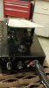
Picture attached shows the controls on the foot pedal which is attached to the welder via a cable about 15 feet long. The V is variable, ie, use the control to the right of the switch to control your welding amperage. The F is full power or what the welder is set to (actually, about 90% ) and the F incorporates the Foot pedal.
This site uses cookies to help personalise content, tailor your experience and to keep you logged in if you register.
By continuing to use this site, you are consenting to our use of cookies.