Electro Tech is an online community (with over 170,000 members) who enjoy talking about and building electronic circuits, projects and gadgets. To participate you need to register. Registration is free. Click here to register now.
Welcome to our site! Electro Tech is an online community (with over 170,000 members) who enjoy talking about and building electronic circuits, projects and gadgets. To participate you need to register. Registration is free. Click here to register now.
Consider this simple circuit:
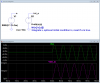
Simulation shows that current through the resistor is alternating, whereas current through the parallel inductor is unipolar. Why unipolar and not alternating?
It is still alternating current, but it is shifted ~330mA. Essentially the inductor "charges" up and discharges through the resistor. I imagine this is what forces it to stay on the positive side. I could do the math, if I could remember all the formulas
Anyway, it is still AC, it's just shifted to the positive side.
Actually with or without that resistor the results are the same. Also if you increase the resistance of the inductor the waferom slowly shifts toward being centered.
I posted a mathematical explanation for this phenomenon here.
Caveat: I am not a mathematician. I'm an engineer, and I learned my math about 50 years ago, so it's rusty.
I don't remember ever encountering integration by parts in my studies (although I may have). I ran across it while trying to figure out what was causing the DC current in the simulation.
It's pretty obvious some of you either didn't believe my explanation, or didn't understand it, or both.
Have a look at the attachment. Yeah, it's still LTspice, but this time there are no inductors involved, so you shouldn't get hung up on what we have been taught about them. Hopefully, you will believe that LTspice wouldn't screw up something as simple as an integral.
All we have this time is the integral of a sine wave that did not start at time=-∞. The start-up gives rise to the Dirac impulse function. The integral of the impulse is a step. Hence, the DC offset.
I'm convinced, Roff. Still not sure though where that leaves us when it comes to running sims which involve coils/transformers. Is it necessary to wait 'a long time' before conditons stabilise? Are the results in the first millisecs/secs unreliable re the real world?
The results are the same as they would be in real world, if you had those parts. The first rule is, if you want real-real-world resuls, use real world parts and circuits. You will never have an inductor with zero resistance and a voltage supply with zero output impedance, so you are unlikely to encounter this waveform. Now if you add some reasonalble resistance, the reuslts will settle much faster.
Yes, I'm finding that. One slight prob is selecting a 'reasonable' resistance. Not all inductive components have specs which include both inductance and (series) resistance, yet alone parallel resistance and parallel capacitance .
Another possibility to mimick the real world is to set the Initial condition of the inductor. If I run it with the IC=0, the simulation starts positive and slooowly settles. If I set the IC according to the final state, that is IC=-30mA for a 60mApp current, then simulation is where it "should be" from the beginning.
Another possibility to mimick the real world is to set the Initial condition of the inductor. If I run it with the IC=0, the simulation starts positive and slooowly settles. If I set the IC according to the final state, that is IC=-30mA for a 60mApp current, then simulation is where it "should be" from the beginning.
This site uses cookies to help personalise content, tailor your experience and to keep you logged in if you register.
By continuing to use this site, you are consenting to our use of cookies.