Continue to Site

Welcome to our site!

Electro Tech is an online community (with over 170,000 members) who enjoy talking about and building electronic circuits, projects and gadgets. To participate you need to register. Registration is free. Click here to register now.

  • Welcome to our site! Electro Tech is an online community (with over 170,000 members) who enjoy talking about and building electronic circuits, projects and gadgets. To participate you need to register. Registration is free. Click here to register now.

A hard to resist problem

Status
Not open for further replies.
A desoldering station would be excellent to own but falls into the decedent category of my lists. To start with you will probably be dealing with through hole components. To start you can do a lot of salvage work and repair work with:

(1) Good soldering iron, preferably with temperature control,
(2) A reel of Soder Wick
(3) Can of rosin flux
(4) Wire cutters precision
(5) Pliers fine precision
(6) Set of electronic tweezers etc (not expensive)
(7) Solder sucker (not expensive)
(8) Reel of solder lead/tin Rosin cored

Some form of vice/clamp would be useful to hold items while you are woking on them
Fortunately I have all them but unfortunately I find using solder wick and a solder sucker really hard to use otherwise I would use them more often. I was going to get a desoldering station before I got the multimeter but then realized I needed the multimeter more.
 
Fair enough, just to say though that I am a chronic savager and have never needed a soldering station, useful as they are. The only time I would get one is for surface mount work, and then you would need a microscope, either electronic or optical. There is a knack to using Soder Wick and a solder sucker. The worry about solder stations is that a half decent one is expensive and a cheap one is not worth the bother. The only solder stations I know about are pro rigs costing thousands. It would be interesting to know what the other ETO members would recommend. In the meantime I will ask around. Do you have a particular solder station in mind and, if so, how much?
 
Last edited:
Fair enough, just to say though that I am a chronic savager and have never needed a soldering station, useful as they are. The only time I would get one is for surface mount work, and then you would need a microscope, either electronic or optical. There is a knack to using Soder Wick and a solder sucker. The worry about solder stations is that a half decent one is expensive and a cheap one in not wort the bother. The only solder stations I know about are are pro rigs costing thousands. It would be interesting to know what the other ETO members would recommend. In the meantime I will ask around. Do you have a particular solder station in mind and if so how much?
Yeah I found the same thing they are either way out of my price range or not even worth the time but I did find one from jaycar that wasn't too bad. It's still on the pricey end of the spectrum but not so bad as to make me want to just not bother https://www.jaycar.co.nz/Tools-&-Soldering/Soldering/Stations/80W-Desoldering-Station/p/TS1513
 
That looks ok, but it is quite an expenditure. One thing that is missing is a heat gun, which are used quite a bit these days. The idea is that you heat the whole board and lift off the components with tweezers. Or you solder paste/flux the pads and stick the components in place with special glue. Then heat the whole board for assembly. Many laptops fail due to solder fatigue/ corrosion on the mother board around the hot areas- graphics chip is favorite. I have come across three so far. The dodge there is to clean and reflux the whole board and then reflow the solder joints with a heat gun or oven. I am really not sure which way to go on this. Have you ever used a solder station like the one you are considering?

I should add that I have only done a few simple surface mount assemblies. The repair work on the laptop boards was done by a pro wireman with all the kit at his disposal.
 
Last edited:
Spec: You put oscilloscope in the category of "luxury items" in your very comprehensive workshop inventory. I can understand on the basis of cost why that might be deemed so. However there are a lot of reasonably good used analogue scopes to be had. Whilst I wouldn't say that a 'scope is essential, it increased my understanding of electronics by a much greater order of magnitude than anything else I've purchased either before or afterwards. Perhaps it depends on your style of thinking, but to me being able to "see" the circuit working and the effect of any changes to the circuit, was the greatest learning tool ever, at least within the realm of electronics. Perhaps since the advent of circuit simulation the use of a 'scope as a learning aid has diminished, but as I'm sure you know simulators and real circuits don't always agree!
 
Spec: You put oscilloscope in the category of "luxury items" in your very comprehensive workshop inventory. I can understand on the basis of cost why that might be deemed so. However there are a lot of reasonably good used analogue scopes to be had. Whilst I wouldn't say that a 'scope is essential, it increased my understanding of electronics by a much greater order of magnitude than anything else I've purchased either before or afterwards. Perhaps it depends on your style of thinking, but to me being able to "see" the circuit working and the effect of any changes to the circuit, was the greatest learning tool ever, at least within the realm of electronics. Perhaps since the advent of circuit simulation the use of a 'scope as a learning aid has diminished, but as I'm sure you know simulators and real circuits don't always agree!

Yes Gordon a very good point.

I am living in the past when a scope simply could not be contemplated because of the cost. Also, I could always borrow a scope from work if needed. As you say, a scope is a revaluation and shows you exactly what the squiggly amps are doing. Now they can be relatively cheap too. I will have another look at that list which is fairly notional at the moment. It also needs rationalization and categorization. If you have any other comments they would be much appreciated.

spec
 
That looks ok, but it is quite an expenditure. One thing that is missing is a heat gun, which are used quite a bit these days. The idea is that you heat the whole board and lift off the components with tweezers. Or you solder paste/flux the pads and stick the components in place with special glue. Then heat the whole board for assembly. Many laptops fail due to solder fatigue/ corrosion on the mother board around the hot areas- graphics chip is favorite. I have come across three so far. The dodge there is to clean and reflux the whole board and then reflow the solder joints with a heat gun or oven. I am really not sure which way to go on this. Have you ever used a solder station like the one you are considering?

I should add that I have only done a few simple surface mount assemblies. The repair work on the laptop boards was done by a pro wireman with all the kit at his disposal.
I don't mind saving for something like this since it will last me for a long time and I've been thinking about upgrading my soldering iron to one that's includes a hot air gun/rework station. This one is the one I'm probably going to get as I have seen it up close and it appears to be very reliable https://www.jaycar.co.nz/Tools-&-So...-Safe-Solder-Desolder-Rework-Station/p/TS1574
 
Spec: You put oscilloscope in the category of "luxury items" in your very comprehensive workshop inventory. I can understand on the basis of cost why that might be deemed so. However there are a lot of reasonably good used analogue scopes to be had. Whilst I wouldn't say that a 'scope is essential, it increased my understanding of electronics by a much greater order of magnitude than anything else I've purchased either before or afterwards. Perhaps it depends on your style of thinking, but to me being able to "see" the circuit working and the effect of any changes to the circuit, was the greatest learning tool ever, at least within the realm of electronics. Perhaps since the advent of circuit simulation the use of a 'scope as a learning aid has diminished, but as I'm sure you know simulators and real circuits don't always agree!
I do want to get one at some point however it's not high on my list yet but if I find one that's won't take much saving I'll probably get it.
 
Hmmm looks well made and comprehensive. That is about £200 UK and personally I would put the money towards a scope. But as this is not really my area don't let me put you off.
 
Hmmm looks well made and comprehensive. That is about £200 UK and personally I would put the money towards a scope. But as this is not really my area don't let me put you off.
As I said I do want to get a scope but I would rather be able to make things and learn about the theory then have a scope and nothing to use it on
 
Yes, Brymen multimeters are brilliant. I thought at first that Justin's multimeter might have been OEM by Brymen but, as I said earlier, I'm now pretty sure it is made by/for Extech.

What model Brymen did you go for?
BM867

Whilst I was researching what to get, I discovered that Extech and Amprobe meters both use Brymen chips.

I think it might help Justin's Great Cause if I list what I've built/acquired in the last couple of years, on wafer thin budget.
  • Soldering iron/station - I got a used Hakko iron (might be a clone) cheap, and built myself a clone of their 936 analogue station from a schematic of the original found on the web. Had to modify it slightly because the triac controller is obsolete. I can post the schematic if you like.
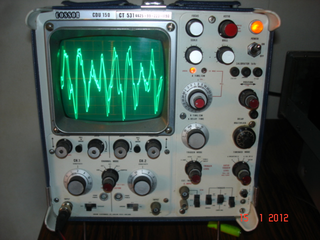
  • Oscilloscope - I got a Cossor CDU 150 for 99 pence. A real high end scope in its day. I bought it as "spares/repairs", bought a copy of the manual for about £20 and repaired it. Needs some more tlc when I have the time.
  • PSU - I built an ATX conversion supply which I used until it died, been using an assortment of wall-warts whilst I get a big home made one up and running. Fun and games and a massive learning experience with that, lots of strange effects I didn't anticipate and didn't show up in simulation. Strangely the badly lashed up prototype gave me about 3mV assorted noise and other garbage, the nicely PCB built version is giving me 10 - 15mV of it. Had a lot of help here with that project :)
  • Assorted small hand tools - all cheap! Mainly I use a pair of long thin smooth jawed pliers with fine tips, and a miniature Xuron side cutter which I'm very happy with. Actually I'm also very happy with a recessed trimmer tool I made from a bit of stiff plastic tube from a soap dispenser with a bit of thin metal pushed into the end. Covered in heatshrink and a nice brightly coloured knob on top!
  • Component tester bought from BangGood. Brilliant piece of kit - discussed elsewhere on ETO
  • Illuminated magnifier - it has a gooseneck stand
  • X10 magnifier. Gets used a lot these days, often in conjunction with the illuminated one
  • PCB making equipment. I use the toner transfer method. Works ok for small boards. Big PSU board came out terrible. I made a mini press drill for pcbs. Experimenting with getting higher spindle speed, thinking of trying a spindle motor from a hard disk
  • The Brymen multimeter mentioned above. I did have a Mastech digital/analogue combo meter. Mastech are ok but the current range is very limited. I say did have, I've still got it but it's become hopelessly inaccurate. At some point I'm going to repair it because it would be very handy to have 2 meters on the go.
  • Voltage reference I made using a precision reference chip with a small pre-regulator and low battery indicator. I built it to calibrate the Mastech meter before it went completely wrong.
  • I built Mr RB's small capacitance meter. I don't think my build does the design justice though.
  • Multipurpose crimping tool with assorted insulated terminals
  • I did start a homebrew digital multimeter project but it's been shelved for now. The digital part works. My signal generator exists as a series of notes and outline drawings in my Designing Things Book. Frequency meter in a somewhat less developed state...
  • Big stack of scrap pcb's I am slowly stripping parts off.
  • Various parts stripped off scrap pcb's
If you haven't fallen asleep by now... I think the "pico scope" and similar are probably good for beginners on a tight budget. You plug it into your laptop or whatever. Limited bandwidth but better than nothing.

Re: hoarding. Guilty. Though mainly my hoard is just stuff I haven't got round to dismantling yet. My workshop is an 8' garden shed which I use for woodworking and metal bashing as well as electronics, so I have supplies for those interests as well. It's cramped.
 
Last edited:
Hell throb,

You have done some work in electronics- I'm jealous. For various reasons I haven't had a workshop for the last three years but every so often I crave a snort of the old Rosin. A couple of days ago I repaired the laptop PSU so had a quick fix then.


Nice machine- jealous again

**broken link removed**

  • Whilst I was researching what to get, I discovered that Extech and Amprobe meters both use Brymen chips.
Interesting- so I was on the right track

I think it might help Justin's Great Cause if I list what I've built/acquired in the last couple of years, on wafer thin budget.
  • Soldering iron/station - I got a used Hakko iron (might be a clone) cheap, and built myself a clone of their 936 analogue station from a schematic of the original found on the web. Had to modify it slightly because the triac controller is obsolete. I can post the schematic if you like.
Sure- like to have a look. I have messed about with Weller temperature controllers- mainly cracked PCB. I think the circuits are all similar

  • Oscilloscope - I got a Cossor CDU 150 for 99 pence. A real high end scope in its day. I bought it as "spares/repairs", bought a copy of the manual for about £20 and repaired it. Needs some more tlc when I have the time.
Ditto, except Gould OS1000 @ £5 UK. You just don't care how much dosh you splash about, do you...99p. What more needs to be done to your scope?

dsc07588.jpg

  • PSU - I built an ATX conversion supply which I used until it died,
Yes, ATX PSUs can be a bit temperamental if they are not configured and loaded to their specification and they are all different.

whilst I get a big home made one up and running. Fun and games and a massive learning experience with that, lots of strange effects I didn't anticipate and didn't show up in simulation. Strangely the badly lashed up prototype gave me about 3mV assorted noise and other garbage, the nicely PCB built version is giving me 10 - 15mV of it. Had a lot of help here with that project :)

What type of PSU? Switch mode?

  • Voltage reference I made using a precision reference chip with a small pre-regulator and low battery indicator. I built it to calibrate the Mastech meter before it went completely wrong.
V ref very handy- be interested to see schematic
 
Last edited:
I'd hardly call it having done some work in electronics. Never done it professionally, just an enthusiast.
The scope has flaky controls mainly. Keeps getting damp in the shed too - doesn't like that. One of the w/w pots inside used for calibration has a bad spot on the track around the set point so I can't set it up quite right. Need to reverse the track end connections. Oh also one of the polarity swap switches disintegrated, can't get slide switches with the correct pin spacing so it's got an audio "push on, push off" switch there for now (except fitted backwards and tied to the panel control so it's "pull on, pull off".)
The PSU has a switch mode pre-regulator and linear output regulator. Been discussed here quite a bit so I won't go into it. it's fun and games with the current limiter I'm having, and a novel output protection I came up with - had to scrap the idea because it interacts with the current limiter and destroys output transistors. Ooops. I'm somewhat unwilling to post it in case anyone builds it as is and Something Bad happens.
Reference: This was when I hadn't done any serious electronics for a long time so it's rather feeble minded. The Mastech meter is 3.5 digit so the reference had to be able to output less than 2V. I got a 5V reference chip because percentage-wise it was the most accurate. I used high precision resistors to make a p.d. to get the low voltage output - worked out that it would be possible but highly unlikely that the accuracy was made worse or better (but most likely to be the same) - and bunged a voltage follower on the output so that the loading of the meter's input in parallel with the bottom resistor wouldn't affect output voltage. Of course it's likely that the follower introduces an error all of it's own, defeating the object. Always one go to for versatility I also put a crappy adjustable (poor man's multi-turn) output on it - which would have to be set using a meter of course.
Soldering iron controller. I used 2x LM358 because I didn't have an LM324, which is what they used in the original. Excuse my layout program's crummy symbols I hadn't got round to making ones showing separate amps at this point. It's possible the comparator is shown wired the wrong way, I know I messed about with it a lot after I built it. Compare with the original schematic I found on the web (2 versions - I think the big red arrows are to do with a forum thread I found it on). It's the uPC1701C that's obsolete, but it's little more than what I actually used.
 

Attachments

  • 936-clone-schematic.pdf
    29.5 KB · Views: 268
  • Hakko 936 Schematic small.jpg
    Hakko 936 Schematic small.jpg
    47.4 KB · Views: 355
  • HAKKO_936_schematic.pdf
    681.8 KB · Views: 166
  • reference-final-1-1.pdf
    109.6 KB · Views: 148
Last edited:
Cool. Everyone quit PMS-ing.

For a solder/desolder station **broken link removed** these are not too bad. I have the BK 6000 which isn't made any more, but I got hot air, de-solder hot iron and an arm.

==
Justin does have an application for a scope. Fix the guitar thigy. He should try to get a schematic and/or find out what the cost of repair is from the manufacturer.
Then maybe try to determine what OP amps are used. Maybe one of the things he could do, is check the offset and he difference of the +-inputs of all of the OP-ams.
That's something that could be done now with a meter.

==

Troubleshooting when you have a schematic generally involves injection and/or tracing once the power supply and power supply ripple have been checked.
You generally start in the middle and bisect the failed stages. This results in the fastest fault finding. With stereo stuff, you sometimes have another good channel to compare.
You also might have to draw the circuit.

==

I got an HP200C (one of HP's 1st audio oscillators) for free. https://hpmemoryproject.org/wa_pages/wall_a_page_01.htm ebay price is like $500.00 USD.

Later, I got one of these: https://www.amazon.com/Tenma-72-505-Hand-Audio-Generator/dp/B008DJS2GY
because I was servicing audio amplifiers. I do have a full 20 MHz function generator, the PM5139: **broken link removed**

==
 
As I said I do want to get a scope but I would rather be able to make things and learn about the theory then have a scope and nothing to use it on

I got by for the first 17 years of my life without one. Apparently I started playing with "wires" when I was about 3, so can maybe say I got by for 14 years, anyway, you can go a long way with just a multimeter, my first one was very basic, analogue with about 6 options! I got given a good quality one from a neighbour who worked as an electrical engineer on a ship, that helped make progress, but as I said before, a 'scope helped so much to further my understanding. It might be possible to side step this using circuit simulation software. A power supply is a good investment, as replacement batteries are expensive, in the long run. If you must use batteries at least buy rechargeable ones and of course, a charger.
 
Last edited:
Apparently I started playing with "wires" when I was about 3

Yep, me too, but ersatz wires. I had to have a string on things that plugged in like a play iron.

This guy **broken link removed** was pretty neat. It's an LM317 based supply that changes transformer taps based on voltage selected. Mom had a transistor radio that hummed like crazy with wall warts. With this, it's been quiet. I like to have a few more.

Here is another idea that I seen to give you two unregulated voltage options, this can then feed into a linear regulator like an LM317. In the position shown the output voltage is X1/2 with it in the other position it is X1. ( e.g. for a 12-0-12 volt transformer. First switch position; Vcc = 16~17 V, in Position 2; Vcc= 32~34 V ( unloaded voltages ))
The contacts can be operated manually by a switch or automatically with a relay controlled by a comparator that switches according to the required output voltage.

Voltage Switchable Rectifier.png
 
Last edited:
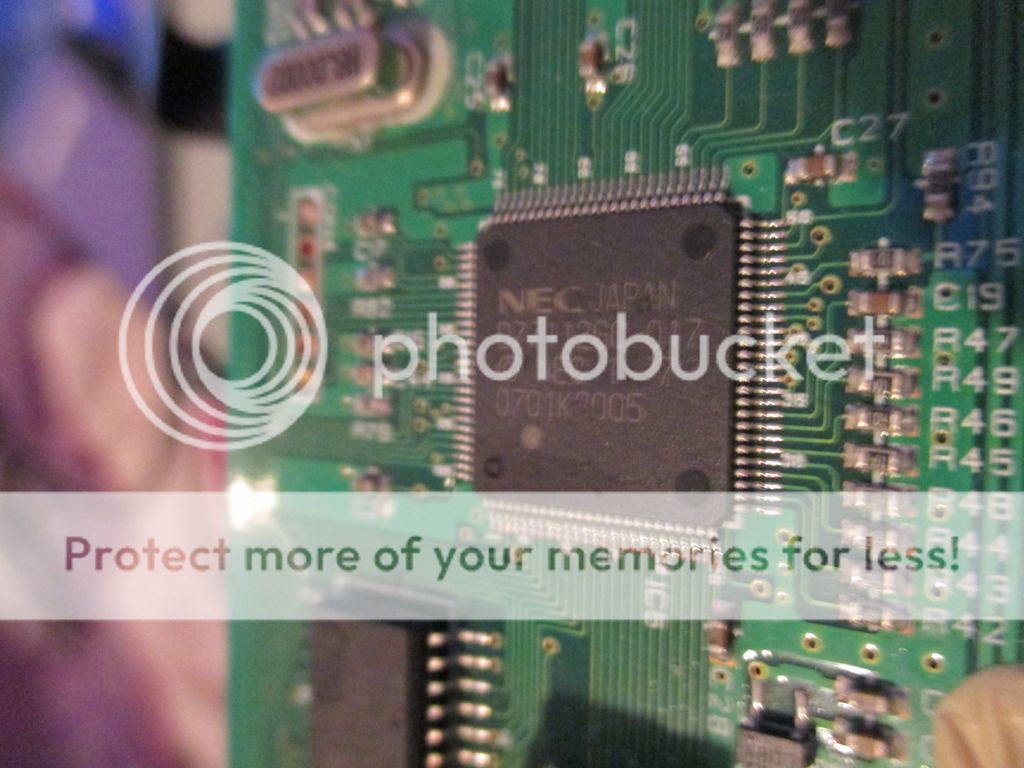
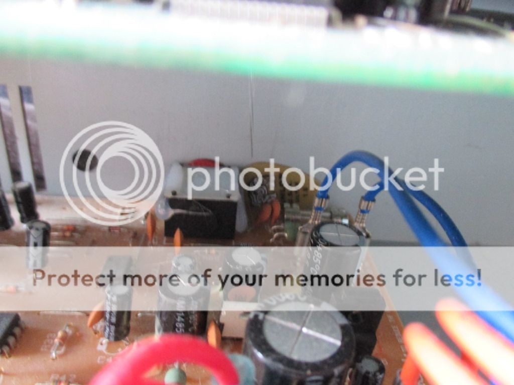
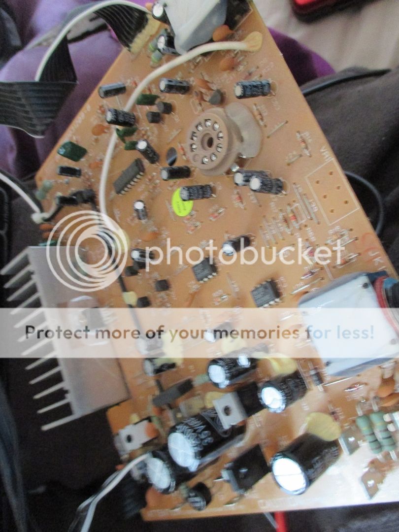
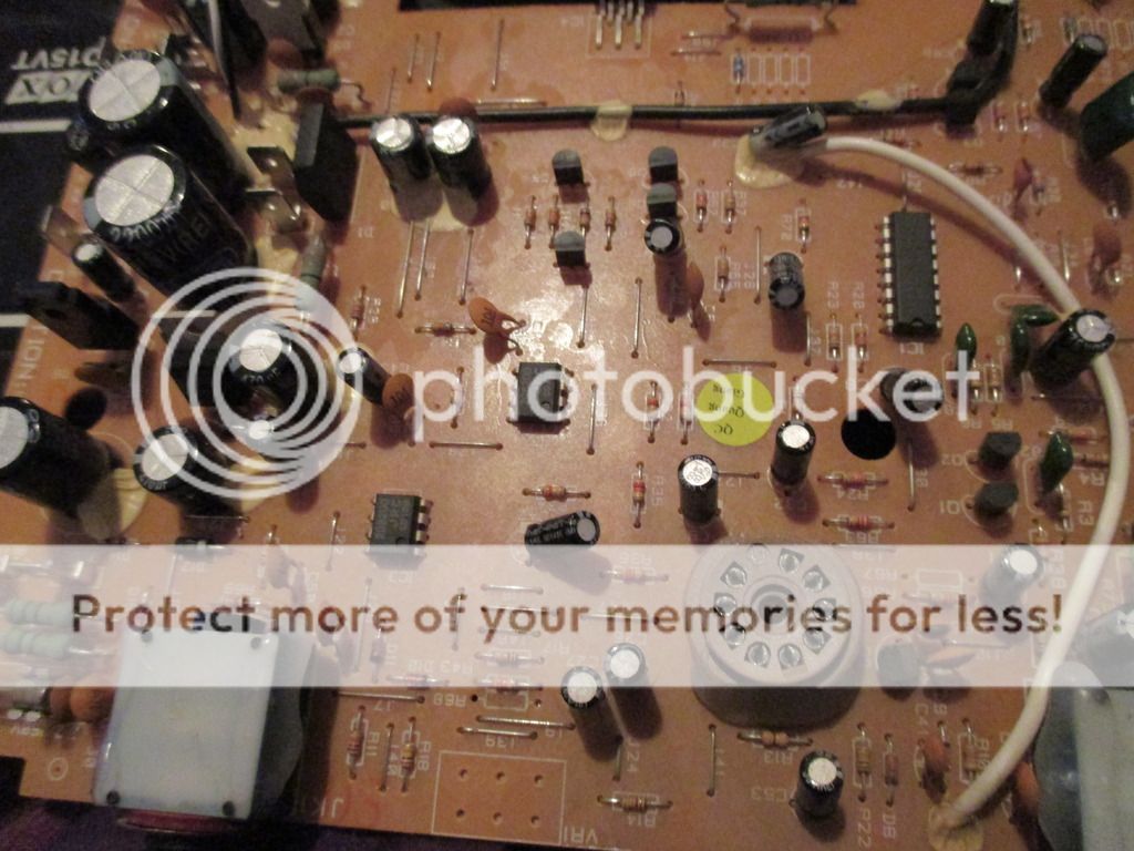
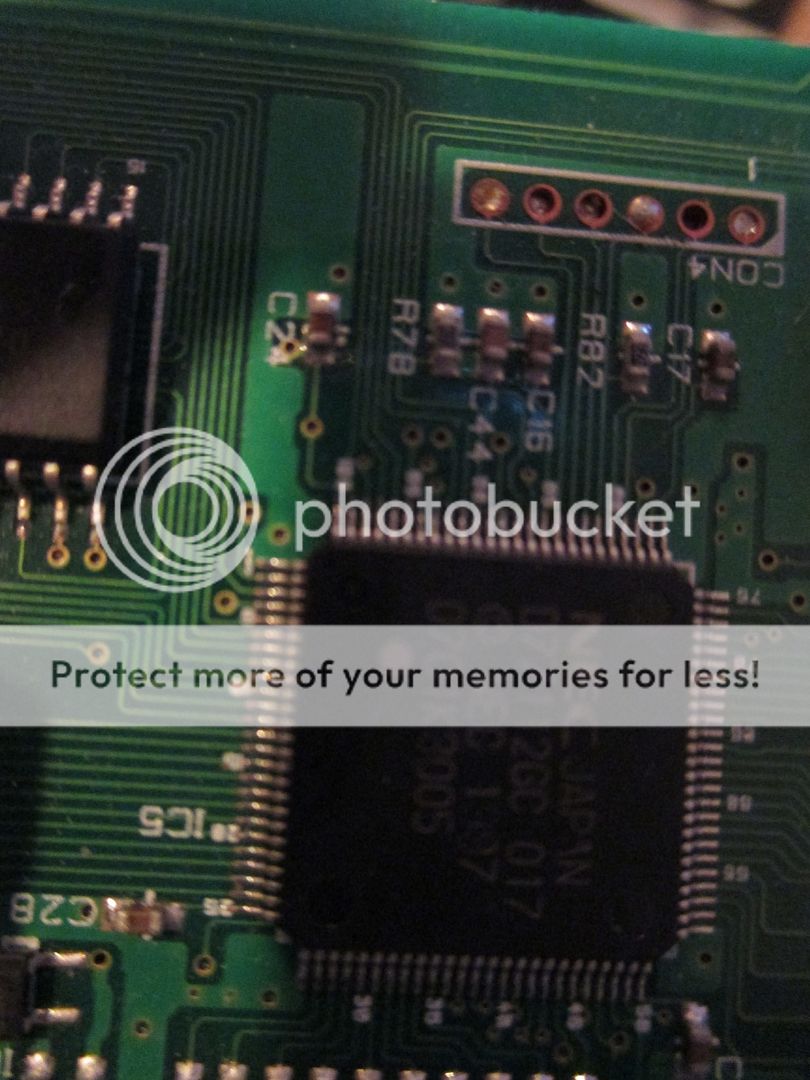
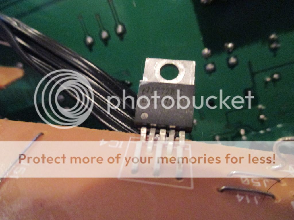
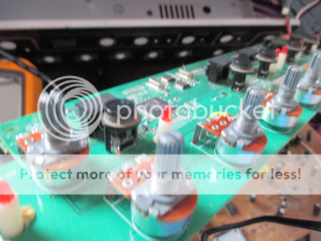
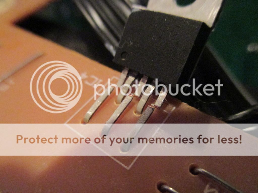
Hey I have been given this amp (a vox valvetronix ad15vt) that I can have but I need to fix it. When I turn it on it works fin but when I turn it down the volume jumps way down but doesn't jump back up when I turn it up. It also drives itself really weirdly even at low volume. I've taken it apart and taken some photos of it but all I have found is one conponint has broken at the legs but I think that might have been me when I was unscrewing everything. If I could get some help with where to start or how to go about fixing it I would be very happy. I'll post photos up below.
IMG_1979.jpg
IMG_1970.jpg
IMG_1971.jpg
IMG_1980.jpg
IMG_1977.jpg
IMG_1978.jpg
IMG_1975.jpg
IMG_1972.jpg
IMG_1976.jpg
IMG_1973.jpg
 
You could replace the IC https://www.ti.com/lit/ds/symlink/lm1875.pdf or repair the pins. The DC offset voltage would be an indicator if it's working

Coupling caps like C1 in the above woud be prime suspects. They really should be metalized polyester caps, but for cost reasons electrolytic are used.

Caps like C2 will also affect the gain. It sets the low frequency response.

2.2. met film 5% is $1.23 USD **broken link removed**

There's a big difference in price and tolerence: **broken link removed**

I see a missing tube - that's probably intentional.

Freeze spray may help in this situation.

So can the component tester with an ESR function. Sometimes the capacitance can be way off. You can use your new meter for that/

I'd look at the < 2.2 uf electrolytic caps first after replacing/repairing the AMP IC. Inspect carefully for bulges.

The smaller IC's may be OP amps. They may not have real numbers on them. Sometimes they are hard to identify. The difference between + and - should be close to zero unles s used for other functions. The output offset is something else to check.

Helping someone service something usually doesn't turn out to well. These are general recommendations.
 
Status
Not open for further replies.

Latest threads

Back
Top