Continue to Site

Welcome to our site!

Electro Tech is an online community (with over 170,000 members) who enjoy talking about and building electronic circuits, projects and gadgets. To participate you need to register. Registration is free. Click here to register now.

  • Welcome to our site! Electro Tech is an online community (with over 170,000 members) who enjoy talking about and building electronic circuits, projects and gadgets. To participate you need to register. Registration is free. Click here to register now.

7 segement 74ls90 debouncing

Status
Not open for further replies.

tempy111

New Member
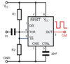
Hi.. i'm trying to built a fairly basic 7 segment counter based on the attached plan.
Problem i'm having is debounce (i think).. the button actives on release i believe, or atleast thats when the segment updates. but sometimes it's a smooth count up, other times it's a bit jumpy, which seams like debounce behaviour to me.

I've tried to add a 0.1uf (104) ceramic capactor both over the switch (from the one pin to the other (top right to bottom left of the 4 pins on the switch) to deal with it, OR going from the top right to just onto the ground rail, but all these seams to do is create a bigger and a bit more stable bounce. it now counts from 0 to 2, to 4, then sometimes to 8 other times round to 2 or 0.

I'm wondering if i just screwed up the capactor for dealing with the bounce or... I'm not quite sure.. any advice?
 

Attachments

  • segment12.gif
    segment12.gif
    17.9 KB · Views: 240
mmm annoying.. circuit says it should be fine but okay.. need to add extra bits like that..

i though the 1kohm resistor was meant to be helping for part of it but oh well..

anyway.. not got any real experience with Schmitt triggers.. All i know is that they are little circuits that kinda use a transistor like effect? i probebly got everything else laying around..
 
mm... so... if i follow this right, and doubled check up o the RC debouncer circuit.. if the switch, instead of output going to ClockA and the i think pull down resistor (1kohm), i should have the switch going to a resisitor and a capactor running parallel, then to the clockA and 1K.. to help with the debounce..

power source is 5v.. well, i'm using a 3.7 small li-ion pack which powers it nicely. so.. the values would be... 500ohm resistor and a 10nf ceramic capacitor (103 i think)? sorry, my maths is a bit lacking (I'm mostly a programmer and art guy ^_^)..
probebly a bit lower then them values..
 
While a properly debounced input is a good idea, the reason adding a capacitor to your circuit did not help is that the capacitor is too small. The time constant for 100 nF and 1 K is only 100 us, while switch bounce can go on for many milliseconds. As a test, increase the capacitor to 100 uF uF. It will slow the response to the switch enough to notice, but it also should greatly reduce or eliminate the bounce effects. If yes, then reduce to around 22 uF as a compromise between bounce reduction and response time. Typical debounce times are 20 ms for small switches, and 50-100 ms for big fat bouncy industrial types.

Also, add a 100 nF capacitor across the power pins of each active device. Keep the leads as short as possible.

ak
 

The RC circuit on page 2 may well be all you need.
 
mm.. okay, i put a 100uf capactior in circuit but i think i screwed up the placement.. i put between the 'out' of the switch and the wiring going to the ClockA and the 1kohm resisitor but... i kinda jumped and then does nothing when i press the button.. so clearly in the wrong place..
 
mm.. okay thanks but.. put it in parrallel with the 1K resisitor (see original circuit for that) and.. if the display is 0, it jumps up to 2, and then either does nothing or i have to hold the button down and it a jumps a bit more... sorry. really can't see what i'm doing wrong..
 
mm... so... if i follow this right, and doubled check up o the RC debouncer circuit.. if the switch, instead of output going to ClockA and the i think pull down resistor (1kohm), i should have the switch going to a resisitor and a capactor running parallel, then to the clockA and 1K.. to help with the debounce..

Where is the Schmitt trigger? - that's what makes it debounce.
 
okay.. i know you said about that, but then the stuff with that RC circuit seamed to say there are other ways and i'm starting to get a tiny bit confused here.. sorry ^_^;
 
okay.. i know you said about that, but then the stuff with that RC circuit seamed to say there are other ways and i'm starting to get a tiny bit confused here.. sorry ^_^;

The other way is suggested was a two way switch and a flip/flop - the RC circuit shows a Schmitt trigger, and specifically states so in the text.

Many of the later PIC's allow you to set the I/O pins to Schmitt or TTL, and setting them to Schmitt allows easy hardware debouncing.
 
ugh.. this 74ls90n is more confusing then expected...

trying to see if there are any IC packages that might work.. something about 555 can be used as a Schmitt trigger?
 
Okay.. used a circuit for a schmitt using a 555. I need to connect it up.. so.. what i do is have the switch output go to a capactior and a resistor in parrallel, and then have the ends go to the input for the schmitt, and the output for that, going to the clockA pin right?

values for the RC capactior and resisitor.. 100nf and 1kohm?
 
okay, i used the below circuit to create what is meant to be a schmitt. I used 220ohm resistors and a 103 (10nf) ceramic capacitor. I connected the 'output' of the switch to a 1k ohm resisitor and 100nf capacitor in parallel and the outputs of them to the input in the attached circuit. the output of these was then attached to the original circuit where it goes to the clockA pin and the 1kohm resistor before the ground rail.

and now pressing the button does nothing... either i got something wrong with this or.. well.. i got something wrong but i'm not sure what..
 

Attachments

  • 555_Bistabielschmitt.png
    555_Bistabielschmitt.png
    33.5 KB · Views: 178
The schmitt I used was a 40106 (this has six in total), you also seem a bit obsessed with low values? - what's with 1K resistors?.

The 40106 has been removed now, and the PIC replaced with a later version which has internal schmitt inputs - if you switch the inputs to TTL, it doesn't work.

Value wise - I use two x 22K resistors and 1uF multilayer ceramic for the key pad inputs, and for the signal input I use two x 22K and a 0.01uF ceramic, as it needs to be MUCH faster than the key pad.
 
I'm not very good with working out the values but most stuff i toy with normally uses lower values..

And the original circuit for the counter said 1Kohm resisitor going from the switch/clockA to ground, so that's what i used and apart from the jump issue it's fine.. though sometimes i can get the counting pretty well..

I don't have any 40106s though they look a little overkill but then, that's nothing to bother about.. can't see why the 555 setup isn't working through..
 
okay, i used the below circuit to create what is meant to be a schmitt.
That is not suitable as it is.
Swap the capacitor and R2 and connect the switch between the input and ground /0V

R2 should be a low value and R1 a higher value, eg. 1K and 10K, or 100 Ohms and 1K.
Then the cap eg. 10uF with the higher values or 100uF with the lower values.
 
Status
Not open for further replies.

New Articles From Microcontroller Tips

Back
Top