Continue to Site

Welcome to our site!

Electro Tech is an online community (with over 170,000 members) who enjoy talking about and building electronic circuits, projects and gadgets. To participate you need to register. Registration is free. Click here to register now.

  • Welcome to our site! Electro Tech is an online community (with over 170,000 members) who enjoy talking about and building electronic circuits, projects and gadgets. To participate you need to register. Registration is free. Click here to register now.

+-5v Supply from two 7805's

Status
Not open for further replies.

RawDR

New Member
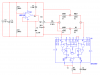
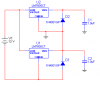
I'm trying to power a INA114 instr. amp from two 7805 regulators. Basically what I want is a signal conditioner/amplifier on one board requiring only four connections: Vpower+, Vpower-, Vsig+, and Vsig-. I've connected the 7805's so the output from the first joins the 'common' for the second, making this node 0V or ground for the rest of the circuit.

At first, it seems to work fine - the output of the two regulators are about equal and the total combined output reaches 10V at around 11.5V input from the main supply. But as soon as you cross this threshold, the output begins to go back down as you continue to increase your input voltage. i.e. at 12V input its under 9.8V output and at 13V input its around 9.5V. Why would it do this?

I also noticed that the second (upper) 7805 gets just a bit warm whereas the lower one stays room temperature. I haven't figure out what would cause that disparity.

Is this a plausible way to power an instrumentation amplifier?

edit: Forgot to attach a schematic.
 

Attachments

  • ampps.PNG
    ampps.PNG
    7.1 KB · Views: 3,541
Last edited:
The problem is that U1 can't sink the current and trying to make it do so will destroy it.

To make a 5-0-5V power supply, you need either two batteries or a virtual earth which can be made from a couple of transistors and an op-amp.

You'll need to use a negative regulator for the -5V (which will only sink current). They also both need to be low dropout regulators, assuming it's a 12V lead acid battery and the voltage will never go below 11V, you need a dropout voltage of at least 500mV.

Q1 and Q2 can be general purpose transistors but you'll need to use power darlingtons if you need more than about 60mA (this is a assuming the transistors you use have a gain of 20 @60mA and can hapilly dissipate 360mW).
 

Attachments

  • Virtual Earth.GIF
    Virtual Earth.GIF
    4.2 KB · Views: 2,998
I see most virtual earth circuits I find on the web don't include the transistors on the output that I see in your circuit. Are these solely for adding source/sink current capacity or what?

My project is designed mainly for use in a lab environment, with regulated power supplies. If I understand correctly, I can simply use this virtual ground with a single regulated 10-20V input to provide a +/- supply to a transducer or wheatstone bridge as well as the INA114 signal amplifier IC. In a wheatstone bridge, power consumption may be relatively high with a 120-Ohm strain gauge, but this won't be an issue because this current is all handled by the PSU - right? The virtual ground should only be used for filtering caps and Ref for the INA114.
 
Maybe not appropriate... but aren't 78xx series Positive regulators, and 79xx negative regulators? You would need one 7805 and one 7905. I know there are a lot of work arounds with these regulators, so might not be important...
 
It would be simpler, probably cheaper and take up less board space to just power it from a small switching regulator with + & - outputs.
 
Maybe not appropriate... but aren't 78xx series Positive regulators, and 79xx negative regulators?
Yes and yes. The 7805 will source current from its output, while the 7905 sinks current into its output. And on the 7905, the output is of course 5V lower than ground. Tunedwolf has the right idea too. Maxim-IC makes a series of switch-mode inverter/regulators that can generate ±5V, ±12V, and other levels from a single 5V input.

If this is coming from the lab's PSU, then those points are moot. Your supply might include a "compliance" setting to limit current to a safe range. But I'd check the manual because it's never a safe assumption. Also double-check that every resistor in the bridge (including the strain gauge itself) is rated for the power they're going to dissipate.
 
Last edited:
Yes, you do need both a positive and negative regulator but the LM7805 and LM7805 are totally useless here because their dropout voltage is too high.

I see most virtual earth circuits I find on the web don't include the transistors on the output that I see in your circuit. Are these solely for adding source/sink current capacity or what?
That's right, most virtual earth circuit are only designed for small signals, <10mA, how much power do you require?

My project is designed mainly for use in a lab environment, with regulated power supplies. If I understand correctly, I can simply use this virtual ground with a single regulated 10-20V input to provide a +/- supply to a transducer or wheatstone bridge as well as the INA114 signal amplifier IC. In a wheatstone bridge, power consumption may be relatively high with a 120-Ohm strain gauge, but this won't be an issue because this current is all handled by the PSU - right? The virtual ground should only be used for filtering caps and Ref for the INA114.

If the postive and negative loads ballance then the virtual earth doesn't do anything. It only dissipates power when more power is being drawn from the positive or negative rail.

If you're powering this from a regulated supply, then you don't need any voltage regulators; for example if you need +/-5V then just use a 10V supply.

If the earth current is very small (within the output current rating of the op-amp), then omit the booster transistors.
 
Update

Okay, I've breadboarded my amplifier. In the schematic it shows a AD624 amplifier but I'm actually using a Burr-Brown INA114 - MultiSim didn't have one.

The wheatstone bridge is going to be made using 2-position PCB terminal strips - this way the resistors can be strung between them or omitted altogether to allow the use of strain gauges in quarter/half bridge configuration or a transducer. The potentiometer is for manually balancing the bridge right before acquiring data.

I've put my RC low pass filter after the amplifier - Are there any arguments for instead putting one on each input just before the amplifier?
 

Attachments

  • amp.png
    amp.png
    30.2 KB · Views: 1,397
Last edited:
hi,
Where are you taking the output from on the AD624.?
 
Maybe useful?

Hi,

I remember T.I. having some great i.c.'s that you would have a normal single rail input, and inside the module, it would convert it to a dual output.

Here is a pdf link for one of the models.
https://www.electro-tech-online.com/custompdfs/2008/05/pt5060.pdf
It operates with a 5v input, and depending on the module, it would either be ±12V or ±15V. You should then be able to adjust the output with resisters. I guess you can search if they have more suitable models for you.
 
is the output on the LM324 actually connected to ground? Sorry realised that is your virtual ground
 
Last edited:
Status
Not open for further replies.

Latest threads

New Articles From Microcontroller Tips

Back
Top