Continue to Site

Welcome to our site!

Electro Tech is an online community (with over 170,000 members) who enjoy talking about and building electronic circuits, projects and gadgets. To participate you need to register. Registration is free. Click here to register now.

  • Welcome to our site! Electro Tech is an online community (with over 170,000 members) who enjoy talking about and building electronic circuits, projects and gadgets. To participate you need to register. Registration is free. Click here to register now.

556 Blinking Light Project help

Status
Not open for further replies.

Mouse51180

New Member
This is my first electronics project. I am trying to do the 555 / 556 Timer IC circuit for a halloween project I want to do, but my LED wont blink.

Here is the tutorial I am trying to follow:
https://www.youtube.com/watch?v=bJa0oiV6B24&feature=player_embedded#at=103
(yes I realize this is a 555 tutorial and I am using a 556 chip...I have got a schematic of both to match the pins)

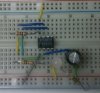
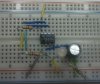
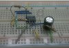
Here is what my breadboard looks like:
**broken link removed**
The cap is a 6.3v 100uF and the resistors are 12Ohm if I am reading the bands correctly.

Oddly enough if I pull the resistorfrom pin 14 and 1 the LED comes on, but no blink???
**broken link removed**

Any help is appreciated...:confused:
 
I can't be sure because I'm reading this post on my phone but the color bands look like brown-red-black. If that's the case then those are12Ω not 120Ω resistors.

EDIT: Also, even if the resistors are correct, 2 120Ω resistors and a 100µF cap would produce a frequency of about 60 Hz which is a little faster than humans can see. Change the resistors to 5 kΩ and that should make the LED blink at about 1.5 Hz.
 
Last edited:
I can't be sure because I'm reading this post on my phone but the color bands look like brown-red-black. If that's the case then those are12Ω not 120Ω resistors.

EDIT: Also, even if the resistors are correct, 2 120Ω resistors and a 100µF cap would produce a frequency of about 60 Hz which is a little faster than humans can see. Change the resistors to 5 kΩ and that should make the LED blink at about 1.5 Hz.

First of all, yes--the resistor you have is 12 ohm, which is way to small. Your LED is blinking, but it is flashing too fast for you to see. Try using a 1K resistor instead (brown, black, red). This should solve your problem.
Good luck!
Der Strom
 
I swapped out my 12Ω resistors for 1KΩ resistors and the LED didnt come on. Could it be because my 12Ω resistors are 1/4 watt and my 1KΩ are 1/2 watt?
 
The wattage for this doesn't matter. Using a pair of 1 K Ohm resistors and a 100 uF cap should give you about a 4 Hz. flash rate on the LED. Fast but very noticeable. Something has got to be incorrectly wired.

Ron
 
I looked over your pictures and it appears to me that everything is wired correctly. With 2 1kΩ resistors and a 100 µF cap you should definitely be able to see the LED blinking. I built the circuit to show you what it should look like. Here's a video:

Astable 555

One thing you can try to troubleshoot would be to add a .1 µF cap between the control voltage pin and ground. You didn't mention if this is a CMOS or TTL chip. What exactly does the chip have written on it? CMOS are very sensitive to static dischsarge so if it is, maybe you accidently damaged it. Also, the 556 is 2 555s in one package. You could try to build the circuit using what is now the spare 555. Maybe the one you're using now was damaged. You could also try a whole new chip entirely if you have another 556 or even a 555. BTW, what voltage source and voltage are you using?
 

Attachments

  • IMAG0252.jpg
    IMAG0252.jpg
    366.4 KB · Views: 575
  • IMAG0253.jpg
    IMAG0253.jpg
    378.2 KB · Views: 431
  • IMAG0256.jpg
    IMAG0256.jpg
    247.6 KB · Views: 444
Last edited:
I just realized you said you swapped out BOTH 12 ohm resistors for 1K. Instead of that, swap R1 out for 1K and R2 out for 10K. I think if both resistors are 1K, the frequency would be VERY low, which means the LED would be off for a very long time. Try changing this and see if it helps.
Der Strom
 
I just realized you said you swapped out BOTH 12 ohm resistors for 1K. Instead of that, swap R1 out for 1K and R2 out for 10K. I think if both resistors are 1K, the frequency would be VERY low, which means the LED would be off for a very long time. Try changing this and see if it helps.
Der Strom


The video I posted shows a circuit where both R1 and R2 are 1 kΩ.
 
The video I posted shows a circuit where both R1 and R2 are 1 kΩ.

Ok, I may have calculated wrong, then. Sorry for the confusion :p

Could you send a schematic of your board? It may help to see how you have everything connected on paper. Thanks!

Der Strom
 
Last edited:
I will try all above suggestions this evening when I get home and post an update. Thanks for all the help so far.

I am not sure what is on the chip...I just got it from Radio Shack. The power source is a 9v battery. I am affraid I dont have a schematic of the board...I was just following the video tutorial list in my first post, but I will try to jot something down tonight. I am not an electronics wiz (thanks Mr. Obvious) so dont be suprise if you are saying..."Why didnt he just use the ground symbol here?"
 
The cap you are using is only rated at 6.3V and your supply voltage is 9V. The cap won't see the whole 9V but it will see a voltage very close to its rating. Just for good measure, you may want to swap it out with a higher voltage cap.

EDIT:

Just noticed something that could be causing your problem. The resistor you have in series with your LED is only 12Ω. That is WAY too low. The blue LED probably has a forward voltage drop of around 3.5V. That means that when you apply 9V to it:

V = IR → I = V/R → I = (Vs - Vf)/R → I = (9V - 3.5V)/12Ω ≈ 460 mA.

I'm not even sure if a 9V can supply that much current when shorted so the LED may have never seen 460 mA but it almost certainly saw more that the 25 mA or so it should have flowing through it. If you allow too much current to flow through it, it can burn out. But, that's not your only problem. Depending on exactly what type of 556 it is, you could have exceeded it's maximum current too. That very well could have damaged it.

Long story short, there are a host of other potential problems introduced by the 12Ω resistor in series with the LED. Change it to something like 270Ω - 1000Ω and try again. If it still doesn't work, I'd try the spare 555 in the 556 or a whole new chip entirely.
 
Last edited:
Ok...so I went to Radio Shack and bought a new 556 chip just to try. Swapped all my resistors for 1K resistors and put in a 10v - 100u Cap. Still not getting anything... :-\

The 556 chip is the 556CN - Dual Timer IC from the shack. Here is the link to the item number on the website:
https://www.radioshack.com/product/index.jsp?productId=2062597&filterName=Type&filterValue=IC-Analog

The top of the chip has the Ti logo with 88FX41K E4 NE556N written on it.

I drew a sketch of what it all looks like...hope this helps.

**broken link removed**
 
Last edited:
R3 should connect from the output (pin 5) to the + side of the LED. Is that a mistake in just your schematic or in the circuit too?
 
I hunted around my junk box from what feels like 1000 years ago and found a 556 chip, and wired it exactly as you have shown and it all worked as expected.

To get a 50% duty cycle (about 1/2 second on/off) i needed to change R2 to 10K, but it did work with R2 as 1K with a long on and a short off flash period.

Is your chip inserted into the board firmly.

Do you have the chip in around the right way? (as i wired mine backwards to start with DOH!!)

You do have the flat side of the led to ground (pin7)

Is the capacitor inserted the right way around with negative to negative etc.

Pete.
 
That was just an error in the schematic. I have corrected the pic.

I really don't see what you're doing wrong. It should work. The circuit that I built and posted a video of was equivalent to yours. After work, I'll swing by Radio Shack and pick up a 556. The only other thing I can think of between now and then would be for you to connect all the pins of the unused 555 (pins 8-13) to ground. Maybe having them float is somehow screwing up the 555 you are using. I know with some logic ICs that makes a difference but I don't remember in which circumstances or why. At any rate, it won't hurt anything to try that.

Does anything get hot when you try your circuit out? The chip? The battery? Any other components?
 
YEA...its working now.

I took everything off the breadboard reinserted the 556 chip in different spot on the board.
Swapped R2 with a 10K
Swapped the LED with a smaller LED I got last night and now its working.

Im guessing larger LED was the headache in this equation.
Here are the two LEDs I am using. The green one works with the schematic and large clear one does not. Too much resistance? not enough power?

**broken link removed**


So I am guessing if I want a longer blink time use larger resistors...if I want a longer fade time use a larger cap...am I correct on this?


THANK YOU AGAIN FOR ANYONE THAT HELPED WITH THIS ISSUE
 
Last edited:
If you want a longer "on" time with the led increase R1 if want a longer "off" time with the led increase R2, if you want a faster or slower flash rate you can do either of 2 things (1) change the capacitor bigger or smaller or (2) increase or decrease both R1 and R2.
Now you have it working have a fiddle with changing the component values and see what happens.

In your first test you had a 10 ohm resistor to the led so you would have burnt the led out with excess current through it, throw it in the bin as it is stuffed now.

Good to see it is all working for you.

Pete.
 
I thought the big LED might have burnt out..thats why I bought the little ones, but if I tap the large LED lead on the 9v battery it still comes on...I dont hold it on so it doesnt burn out, but if I just give it a quick tap it still lights up.
 
It could have also been a problem with the breadboard itself. I know that my breadboard (a cheap RadioShack special) has some contacts inside that are bent out of shape, and do not connect to the components that I insert. This could have been a problem with yours, as well. Moving the chip may have put it somewhere with good contacts that were not bent.

Anyway, I'm glad to hear you got it working! And, as Pete said, fiddle around with it a bit and see what happens if you substitute components with ones of a different value. Just have fun with it--that's one of the best ways to learn! :D

Der Strom
 
Status
Not open for further replies.

Latest threads

New Articles From Microcontroller Tips

Back
Top