Continue to Site

Welcome to our site!

Electro Tech is an online community (with over 170,000 members) who enjoy talking about and building electronic circuits, projects and gadgets. To participate you need to register. Registration is free. Click here to register now.

  • Welcome to our site! Electro Tech is an online community (with over 170,000 members) who enjoy talking about and building electronic circuits, projects and gadgets. To participate you need to register. Registration is free. Click here to register now.

3x3x3 LED Cube - can i use16f628 instead 16f690

Status
Not open for further replies.
Hello be80be,

I just finished reading the whole post and I think I'm ready to modify the .asm file to work for my 16f872.

I was wondering what program you use to make your schematics ?

Thank you for your help !
 
Last edited:
be80be,

I saw in your code for the PIC16f628 the line


movwf CMCON ;turn comparators off (make it like a 16F84)

Should I let it there for a PIC16F872 and why ?

Thanks, I read the awesome Gooligum tutorials (https://www.electro-tech-online.com/custompdfs/2011/04/PIC_Base_A_1.pdf)

and I think I'll be okay to change the other lines for a 16F872

EDIT : I did the first line changes and I'm not sure of these lines

movwf CMCON ;turn comparators off (make it like a 16F84) ?
org 0x0000 ;org sets the origin, 0x0000 for the 16F628 and for the 16F872 ?
movlw d'50' ;delay 250 ms (4 MHz clock) ( with a 16F872, there is no internal oscillator so I'll need to make an external one. With a RC osc (easier) I can reach 3.5MHZ, would it be engouh ? no ? What would be the code to fit with a 3.5 MHz clock

Again, thanks for your useful comments !

Weepet
 
Last edited:
Finished

Hey guys :D

It's working !

Thanks for the help !

I'll try to post a video of my 3x3x3 LEB Cube with a PIC16F872 soon.
 
Yes, as long as you have enough output on your micro-controller.

5 rows + (5*5) 25 columns = 30 outputs
 
who pic micro-controller ( 16f ) has 5 rows + (5*5) 25 columns = 30 outputs ?
 
I am also interested in this led cube project but I have a 16F88 Pic. Has anyone written an asm or hex file for this chip?
 
It's not that hard to do just set the chips configure and pints up that your going to use and it should work fine with that chip.
 
Hey folks, I am also trying to create this cube with the PIC 16F628 and i have went through all the pages of this thread and downloaded all the files.

It seems that every asm/hex file and every schematic has slight variations with respect to the LED lines.

Can someone point me to the correct combination that will work :)

I appreciate it !!

Pete
 
It's not that hard there one pin on the 16F628 that's can't output 5 volts and thats what made this thread so long lol.

I no longer have code for this but I was going to make a blue one when my leds get here. I'll post working code this week if you want.
 
Thank you so much for your response Burt !!

Perhaps this may be helpful then and save double work, i have downloaded and attached the unique files on this thread asm/schematics.

If you can point me in the right direction id really appreciate it, id like to make a few boards/cubes as gifts for some close people.

Thanks
Pete
 

Attachments

  • 3x3x316f628a.asm
    42.4 KB · Views: 339
  • LED.asm
    42.4 KB · Views: 323
  • new3x3x316f628a.asm
    42.4 KB · Views: 320
  • ledcubeicsp.PNG
    ledcubeicsp.PNG
    9.8 KB · Views: 467
  • 16f628led cube.PNG
    16f628led cube.PNG
    11.1 KB · Views: 1,071
  • Schematic with LED wiring guide.PNG
    Schematic with LED wiring guide.PNG
    91.4 KB · Views: 2,495
  • Schematic with LED wiring guide2.PNG
    Schematic with LED wiring guide2.PNG
    91.5 KB · Views: 832
This will work
Code:
PORTA.2 turns on layer1
PORTA.6 turns on layer2
PORTA.7 turns on layer3
PORTB 0 to 7 are led's 1 to 8 and PORTA.3 is led 9
*Layer sink with a npn and portb sources the power to the Leds.
And this asm
 

Attachments

  • Righ3x3x316f628a.asm
    42.4 KB · Views: 387
Much Appreciated Burt !!

Does the schematic look right to you corresponding to the code given ?

Pete
 

Attachments

  • 3x3x3 complete.pdf
    14.9 KB · Views: 443
Much Appreciated Burt !!

Does the schematic look right to you corresponding to the code given ?

Pete

Pete, could you write the values of all the external components Please.

Thank you.

Regards,
kv
 
I used 150 ohm on the leds and 1k on the npn

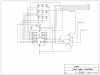
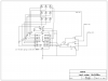
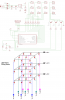
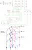
I looked on the other schematics and I think I got that part, I just wanted all the Values displayed on the final to make it easier to read, What value was C2 on VSS? I really like the 2 drawings in Post # 293
 
Status
Not open for further replies.

New Articles From Microcontroller Tips

Back
Top