Electro Tech is an online community (with over 170,000 members) who enjoy talking about and building electronic circuits, projects and gadgets. To participate you need to register. Registration is free. Click here to register now.
Welcome to our site! Electro Tech is an online community (with over 170,000 members) who enjoy talking about and building electronic circuits, projects and gadgets. To participate you need to register. Registration is free. Click here to register now.
ppl,
i need a 3V to 9v converter circuit for my new project, so i want know and learn about them, can anyone post a schematic that is easy to build? I got a 3.7V battery with 750mA current and want 9v or 12V out of it
ppl,
i need a 3V to 9v converter circuit for my new project, so i want know and learn about them, can anyone post a schematic that is easy to build? I got a 3.7V battery with 750mA current and want 9v or 12V out of it
You do realize that the output current will be reduced by the ratio (ideally) of the input voltage to the output voltage. It practice the current will be even less due to converter inefficiencies.
The inverter circuit shown above is only good for 20mA ouput.
For every 10mA output, the current from the battery will be about 40mA.
How much output current do you want?
You modified that circuit. But the schematic you keep posting is the wrong original circuit with 3 transistors so you are confusing everybody.
I posted a circuit with a single transistor that I guessed is the circuit you used. Please post your accurate schematic.
What you are both failing to realise is the fact that these circuits use only a fraction of the supply voltage to produce the output amplitudes. Secondly, the maximum allowable RF energy is only about 10mW to 30mW. These transmitters will reach over 1km on this output power. Anything over 100mW produces lots of technical problems. There is absolutley no need to increase the supply to 9v.
my bad. as guru stated, i modified the circuit using s8050 transistor and got over 2Km of range, but i have to supply 9V for the 2Km goal and that's why i need a boost converter, @guru,
i changed the 2nd transistor with s8050 and removed the final amp transistor, and replaced the v.cap with a fixed "15pf" cap, finally the emitter resistor of 2nd transistor replaced with 100ohm, that is all i modified, @collin, you still didn't mention that the boost conv. Is possible to use with the TX or not.
A fraction of the supply voltage?
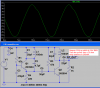
I simulated my FM transmitter RF section:
1) With a 3V supply the output is 3.2V p-p and the power into a 75 ohm whip antenna is 17mW.
2) With a 9V supply the output is 11V p-p and the power into a 75 ohm whip antenna is 12 times more at 203mW.
I used my FM transmitter for only an hour to test its range so the RF cops did not catch me.
I don't think there are any RF cops in Z!dd!k's country.
This site uses cookies to help personalise content, tailor your experience and to keep you logged in if you register.
By continuing to use this site, you are consenting to our use of cookies.