Electro Tech is an online community (with over 170,000 members) who enjoy talking about and building electronic circuits, projects and gadgets. To participate you need to register. Registration is free. Click here to register now.
Welcome to our site! Electro Tech is an online community (with over 170,000 members) who enjoy talking about and building electronic circuits, projects and gadgets. To participate you need to register. Registration is free. Click here to register now.
I replaced surface-mount 14 pin ICs without using extra flux.
I had some defective MP3 players that were "unrepairable" by a store.
I removed a few good parts from one and swapped the bad parts in another and got one working perfectly.
The parts were all tiny surface-mount things but I removed and replaced them without using extra flux.
My usual ones to change are 80 pin, and fairly small spaced - liquid flux is pretty well essential - although an alternative method is to use solder paste.
While waiting for the smt parts, I tired to modify the 'crappy' rf module. I'm using a CMOS NAND gate for the transmitter, when I pull up one input of the NAND gate with a 10 khm:, it doesn't oscillate as expected. So I turn the transmitter on and off using a transistor by PIC. It works at the bit rate of 10 ms. I'm still learning the method of coding and decoding, this is what I can do so far.
I wonder why I can't modulate from the logic gate..
Any NPN transistor will do right? I'll use 2N3904 for this. If I do it this way, can the bit rate be faster? But I don't know whether the poor receiver can receive as fast as the transmitter do or not.
Yes but only when the PLL is tuned exactly to the modulating frequency. If it is not exactly the same then it needs additional time to lock to the modulating frequency.
The super-regen receiver has some capacitors that attenuate its squegging oscillation that might also slow things down.
I think the receiver is designed to slowly switch a relay on and off.
CHEAP, CHEAP, CHEAP, CHEAP stuff works poorly.
I think the transistor is the 300MHz oscillator and it is turned on and off at an audio frequency by the classic Cmos oscillator made from two Nand gates.
The Cmos oscillator can be stopped by diconnecting the input of one gate from the circuit and grounding it, then started with a resistor that pulls the input high.
The transmitting transistor would transmit very low RF power with a low supply voltage. So its range will be small.
An ordinary Cmos gate has a minimum supply of 3V but its output current is very low. A 3V battery's voltage drops to 2V over its life. A 74HCxx Cmos gate has a minimum supply voltage of 2V and has a higher output current.
What good is a transmitter that is not turned on? Hardly ever used like a car door remote entry?
What is a flux residue? Need to clean it up after using the liquid flux?
How do I calculate the frequency of the Cmos oscillator?
Why I can't do it like mentioned previously, just add a pull up resistor. From your schematic, the transistor also acts as a switch right?
The flux basically 'floats' to the top of the soldering joint once the solder hits it and leave a residue over the top of the joint, some types of flux leave a corrosive residue which needs to be cleaned off afterwards. Depends on the flux.
The Cmos oscillator turns on the transmitter and turns it off. Then the modulation is digital AM.
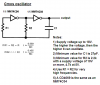
The calculation for a classic Cmos oscillator is here:
MM is an IC prefix used by National Semiconductor so it might have been on their applications note. The same formula is in my "Cmos Cookbook" written by Don Lancaster.
From the attachment, it says that if the supply is higher, the higher it can oscillate, means frequency?
The receiver is really pr
After it is tuned well, the next day or after it has been turned off for a while, I need to re-tune it, or else I cannot get the signal transmitted. And sometimes, no matter how I tune it, it just wouldn't work. Then it worked the next day -_-"
Now it is not working, maybe I'll try it tomorrow..
A Cmos inverter or gate has a higher output current with a higher supply voltage so it can switch faster. I use a two-inverters Cmos oscillator at 1.6MHz on a 12V supply and it works well.
I think your receiver is crappy. Cheap, cheap cheap!
This site uses cookies to help personalise content, tailor your experience and to keep you logged in if you register.
By continuing to use this site, you are consenting to our use of cookies.